
For compliance reasons, it is often necessary to calculate certain building metrics, which Revit cannot do out-of-the-box. One example is calculating an atrium’s area and perimeter for smoke extraction purposes. While this sounds relatively straightforward, it is more complicated than at first glance.
The problem
In AutoCAD, one would draw a polyline and extract the length property. However, since Revit doesn’t have polylines, we would need to draw multiple individual lines and get the sum of all the lengths. Manually trying to do this is not an option because when selecting multiple objects in Revit, no length parameter will be returned (unless all lines are the same length, but even in this case, it wouldn’t be the sum). Moreover, it is impossible to schedule lines, except for Path of Travel Lines, which is not applicable.
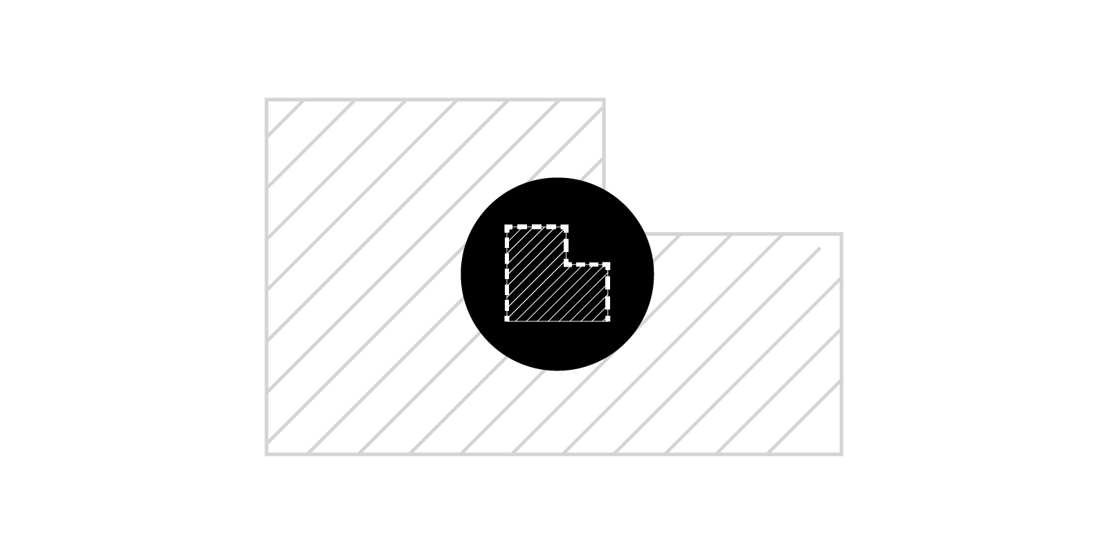
While a room could be placed and the perimeter calculated, this would return the entire perimeter length, which may not be accurate as certain elements, such as stair access points, needed to be excluded from the calculation process. Trying to automate the process with Dynamo wasn’t an option as the atrium wasn’t continuously bounded by a single element of the same category, say a balustrade. Instead, it was bounded by a curtain wall, columns, walls (balustrades) and stairs.

Dynamo automation
It was, therefore, decided that the simplest method to visualise the atrium opening was to create a filled region and use line styles to control which lines to calculate and which to exclude. Dynamo could then be used to extract this information and calculate its perimeter.
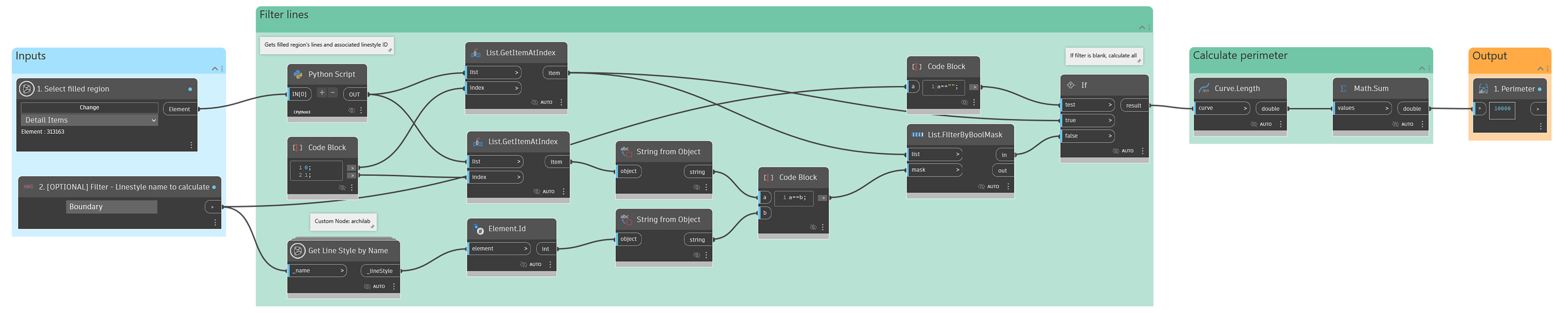
In the example above, the Python node does all the heavy lifting, returning the filled region’s perimeter curves and their associated line style ID. An optional filter removes any lines that aren’t of a certain style, such as “Boundary”. If no filter is specified, all curves are returned. Note that will automatically be excluded. Once all the perimeter curves are known, calculating the total perimeter length is a simple geometric calculation.
import clr
clr.AddReference('ProtoGeometry')
from Autodesk.DesignScript.Geometry import *

clr.AddReference('RevitAPI')
import Autodesk
from Autodesk.Revit.DB import *

import clr

clr.AddReference('RevitNodes')
import Revit

# Import ToProtoType, ToRevitType geometry conversion extension methods
clr.ImportExtensions(Revit.GeometryConversion)

#The inputs to this node will be stored as a list in the IN variables.
element = IN[0]

result = None

revitElement = element.InternalElement

edges = []
lineStyleIds = []

if type(element.InternalElement) == FilledRegion:
  filledRegion = revitElement
  geometryElement = filledRegion.get_Geometry(Options())
  geometryObjects = list(geometryElement)
  for geometryObject in geometryObjects:
    if type(geometryObject) == Solid:
      solid = geometryObject
      edges.extend(e.AsCurve().ToProtoType() for e in solid.Edges)
      lineStyleIds.extend(e.GraphicsStyleId for e in solid.Edges)
    else:
      raise Exception("FilledRegion: has non-Solid geometry!")

#Assign your output to the OUT variable.
OUT = edges, lineStyleIds


