
For a healthcare project, it is often necessary to create a 3D axonometric view per room when creating a room data sheet. As previously shown, this process can be automated using our Axonometric from room Dynamo tool, which enables the user to define the view orientation – NE, SE, SW or NW – and then generate a 3D axonometric (orthographic) view based on the bounding box of the room. But sometimes, it isn’t obvious which is the best orientation before running the graph, and the view orientation needs to be updated after the view has been created.
The problem
While it is possible to quickly and easily change the view orientation using Revit’s in-built view cube, the problem is that the view’s crop region also needs to be updated. This adjustment is required to ensure that the full extents are visible and that the crop region is not excessively large to cause alignment issues when placed on a sheet. The process often is of little concern when only a handful of views are in question. However, this process can quickly become time-intensive when it needs to be done for numerous views, as is frequently the case with room data sheets.
Updating an axonometric crop region with Dynamo
The solution is to use an automated routine to batch update multiple views simultaneously. Our ‘Axonometric Crop Region’ tool, available as part of our Dynamo Package Development service, just does this. The graph adjusts the crop region of selected axonometric (orthographic) views so that the extents match the elements visible in the view, including any buffer offset specified.


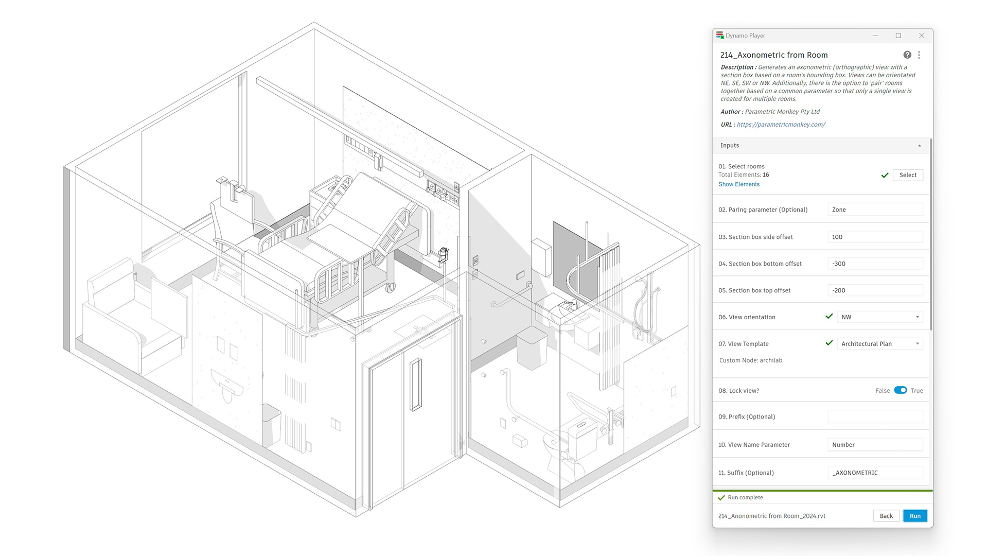
To run the graph:
- Select the views to be modified in the Project Browser. Views should be axonometric (orthographic) views.
- Define the crop box offset (#1). This value is the buffer zone from the elements to the crop box.
- Press Run.
Computational logic
The graph collects the views and filters out those that are not axonometric (orthographic). If a section box has been applied to the view, a bounding box is created, and the vertices extracted. If no section box has been applied to the view, the bounding box of each visible element is calculated (except for cameras, section boxes and levels), and the vertices extracted. The vertices are then projected onto the view plane. Next, the points are transformed back into world coordinates and a new bounding box created with the desired crop box offset (#1).
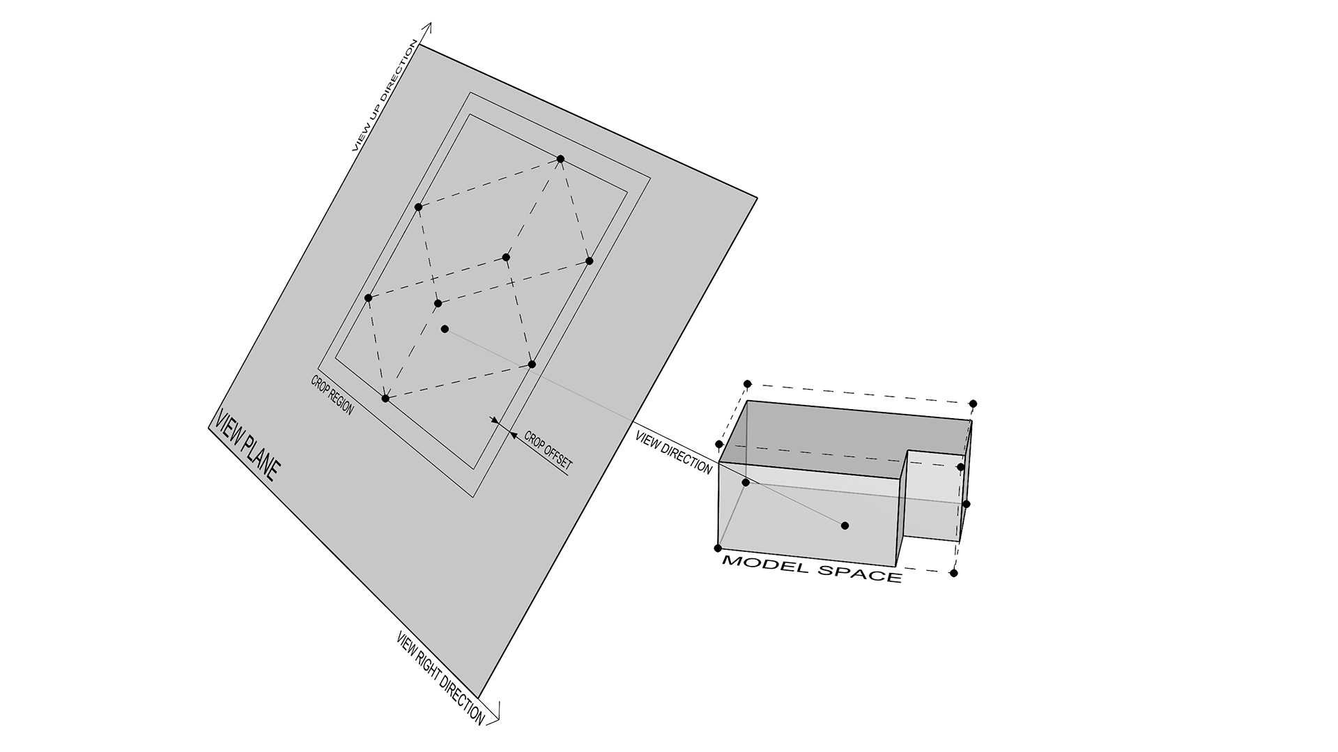
Note, in Revit terminology, the crop box is the 3D element in model space, whereas the crop region is the 2D element in sheet space. To understand more about the relationship between the two, refer to the API documentation about views and View3D.
Conclusion
While automated routines will get you most of the way through a task, creating breakpoints in the workflow for manual invention is often necessary. However, with automated routines such as the one shown above, it is possible to enable manual invention while maintaining accuracy and consistency across your documentation. To learn more about our Dynamo Package Development service, drop us a line and discover how we can automate your Revit workflows.


