
Since establishing Parametric Monkey, we’ve created countless fabrication models for a wide range of projects. While each material was different—sheet metal, stone, timber, etc.—they all shared common workflows that utilised Rhino and Grasshopper. The tips and tricks below are intended to serve as a best-practice guide for creating fabrication models. The aim is to assist the Architecture, Engineering and Construction (AEC) industry in developing design-to-fabrication workflows that enable faster construction, minimise resource use, and employ material-specific design solutions.

Key concepts
Before creating a digital fabrication model, several key concepts should first be understood: Detail versus accuracy, instances versus types, Design for Manufacture and Assembly (DfMA), and the digital pipeline. Each of these concepts is vital to the project’s success. As such, an accompanying rule is defined. Unlike tips, which are best practices but optional, rules must be followed.
Concept #1: Detail vs accuracy
Repeat after me. All digital models are wrong. Even BIM models. Especially BIM models. Even your LOD400 ‘fabrication’ models. Some models are off by a bit, while others are off by a lot. The reasons for this are numerous and include construction tolerances, material deflections, and on-site modifications that were never incorporated into the BIM model. Then there are software limitations. Revit, for example, cannot model anything smaller than 1/32 inch (approximately 0.79mm). Not a problem if you are modelling a wall, but a big problem if you are trying to model a furring channel with a Base Metal Thickness (BMT) of 0.5mm.
However, by far the most significant contributor is the industry’s misguided focus on detail rather than accuracy. And it’s easy to see how this came to be. Clients who want to ‘save’ money often forgo construction documentation. And so, the architect overloads the drawings and model with detail in the hope of conveying design intent. Moreover, by adding detail, issues appear resolved. After all, why would anyone bother detailing something if it wasn’t accurate? And so drawings and models go through the approval funnel to be signed off, the industry’s definition of “DONE”.
It isn’t until someone has to make the physical element that these inaccuracies surface. We’ve seen it all. Set out drawings with thousands of spot elevations; highly detailed, all of them incorrect. Architectural drawings showing intricate patterns and details; highly detailed, but the overall dimensions in plan and section don’t even align. Structural models showing every nut and bolt; highly detailed, but with an inaccurate geometric set-out.
Detail is not the same as accuracy. Detail creates the illusion of resolution, leading to the accumulation of technical debt. Accuracy, on the other hand, fosters trust and enables the ‘golden thread’ of information to flow. Accurate models can always be embellished with additional detail. However, detailed models that are inaccurate cannot easily be made accurate.
Rule #1: Accuracy trumps detail.
Concept #2: Instances vs Types
Most BIM software, particularly Autodesk Revit, has corrupted our thinking about how buildings are put together. For example, within Revit, system families are the fundamental building blocks of most models and include walls, floors, and roofs. While layers and materials can be assigned to the buildup of these elements in the form of a type, they are representations only within the monolithic form. The quantity of individual bricks cannot be measured, nor is any timber or steel framing shown. It is assumed that these will be shown in 2D details, or the contractor is familiar with their construction. System families, therefore, operate at a material level and are documented at an instance level.
Loadable families, on the other hand, function more like parts and are documented at the type level. These could be anything, including doors, windows and toilets. While loadable families can be nested within other loadable families, such as a door handle family nested within a door family, more often than not, the nesting is not very deep. In other words, with rare exception, most BIM models do not consider sub-assemblies or assemblies.

This approach is generally acceptable for conventional construction. However, when it comes to DfMA and Modern Methods of Construction (MMC), it becomes problematic. Elements modelled as individual instances are difficult to document, lack robust version management, and fail to embrace the sub-assemblies and assembly logic central to prefabrication. Digital fabrication models, therefore, require a mindset shift—from instance-based to type-based modelling. Put simply, all elements should be treated as parts. Ideally, these parts are nested within a higher-order assembly, but this will be dependent on the design.

Rule #2: All elements should be defined as parts, and where desirable, nested into sub-assemblies.
Concept #3: Design for Manufacture and Assembly
Digital fabrication closes the gap between digital technologies and the physical construction process by creating a file-to-factory workflow. Central to this process is DfMA, a concept based on a holistic understanding of the production process, including fabrication, transportation, and assembly. A key distinction between BIM and DfMA is that what you see is not always what you get.
In a conventional BIM workflow, we typically care about what it looks like once built. Sure, the model may contain metadata, but its primary purpose is to show what to build, not how to build it. In other words, what you see is what you get (WYSIWYG).
When DfMA is considered, a whole new layer of information is embedded into each part. For example, parts may be unrolled or unfolded and documented in their raw form, as is the case for sheet metal or bent timber. Parts may have a universal grid inscribed on the back as a visual aid to align pieces during installation. Parts may be designed to eliminate the possibility of incorrect installation by utilising a directional, rectangular connection instead of a universal, square connection. And parts might be modelled oversized to allow for on-site tolerances. This information overlay is often not visible once everything is built. But that’s its job—embedded information to make manufacturing and assembly seamless.
Rule #3: Digital fabrication models must embed DfMA intelligence.
Concept #4: Digital pipeline
A good digital workflow requires a pipeline. And the thing with pipelines is that they are directional. Information must flow in one direction and one direction only, as information is inherited as it moves through the pipeline. Consider the following. A change needs to be made to a drawing. One way is to modify the PDF – a quick and easy solution. The problem is that the PDF now becomes the master document. But how does anyone know that? As soon as the PDF is recreated from the drawing, those changes are lost. A better way would be to modify the drawing and then recreate the PDF. But what if the drawings are extracted from a model? As soon as the model changes, those drawing changes are lost. The same applies if a script generates the model. Modifying the script is better than modifying the model.
Pipeline = Script > Model > Drawing > PDF
Not all changes are created equal. Modifying dependents in the pipeline is a surefire way to accumulate significant technical debt and create mountains of abortive work. All changes must occur as high up in the pipeline as possible. The issue, then, is not how to make a change, but how to make a change that enables future changes.
Rule #4: All changes must occur as high up in the digital pipeline as possible.

Tips
It is clear from the key concepts that the best digital fabrication models should be accurate and composed of multiple parts. Each part should have embedded DfMA intelligence. And any changes should occur as high up in the digital pipeline as possible. But how can this be achieved? The following section explores key items and offers best practice tips for achieving a successful outcome. These tips are broken down into four categories: Design, Delivery, Documentation, and Manufacturing.
Design
Reference models vs PDFs
Given that all models are wrong, it goes without saying that all referenced models should be assessed for accuracy. Many contractors will send through PDF drawings and assume that is sufficient for pricing. This shortcut is a recipe for disaster, as not all models are created equally. The original is always the best. It may be a Revit model or a Grasshopper script. In either case, you need the original to assess its accuracy and how easily it can be updated. You can do neither of those things with a PDF.
Tip #1: Request the original Grasshopper script, not the output of the script.
Scan data
Issues relating to inaccurate digital models can often be resolved on-site when using conventional construction methods. However, when elements are prefabricated, these inconsistencies can be the downfall of a project, as everything is designed to fit together perfectly. The best way to mitigate this risk is to obtain a scan of key interfaces to unearth the actual as-built conditions. Ideally, this happens as early as possible, but this isn’t always possible. Interfacing elements may not have been installed yet, or if they have been, they may be concealed behind temporary elements, such as scaffolding, or there may be limited access due to the project phasing.
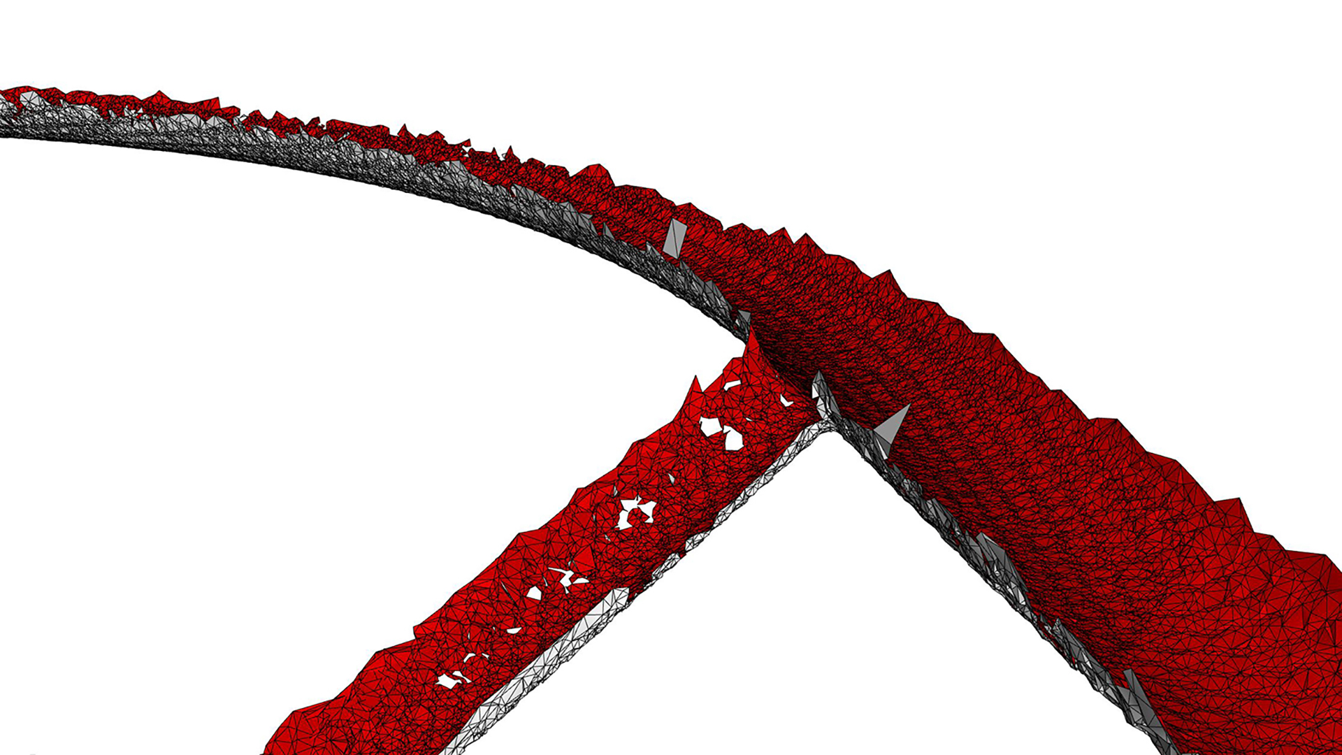
Tip #2: If required, request a scan for the actual as-built conditions.
Parallel models
Since the digital model must progress in parallel, possibly without scan data, it is essential to set up the Grasshopper script to be adaptable. Adaptability can be achieved by enabling the script to run on either the ‘theoretical’ BIM set-out, for BIM coordination, or the real-world condition from the scanned data for digital fabrication. This workflow will allow two parallel design models to be maintained with negligible overhead. Additionally, the script should be developed to accommodate irregular site conditions not represented in the BIM model, such as elements that should be orthogonal but aren’t.
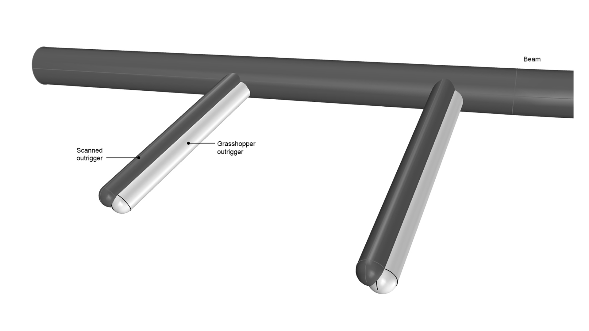
Tip #3: Enable the Grasshopper script to run on either the ‘theoretical’ BIM set-out or the ‘real world’ scanned data.
Substructure
One common misconception about complex geometry is that once you have the form, the rest is easy. In fact, what we’ve found is the total opposite. It is often the parts that you don’t see that are the most complex and time-consuming. They literally do the heavy lifting. And for this reason, substructure is the unsung hero of complex geometry.

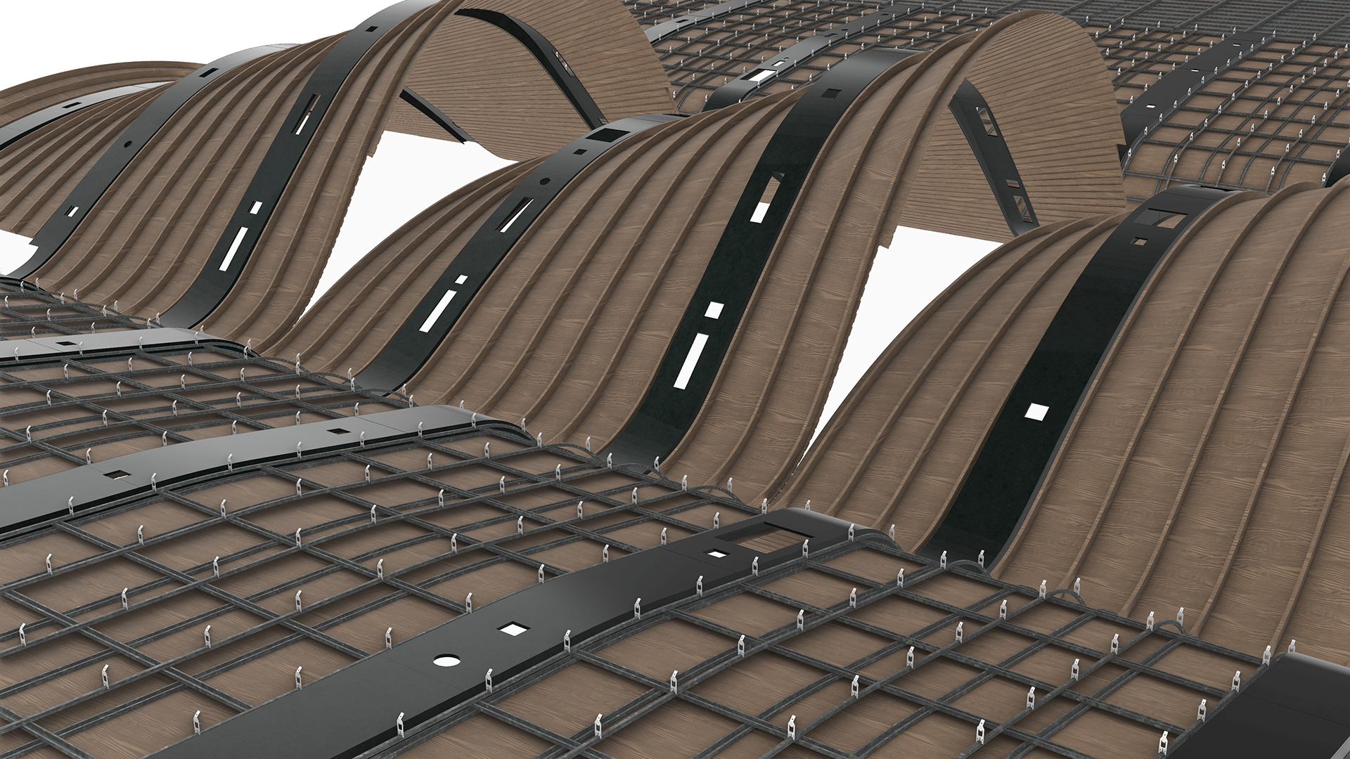
While it is nice to imagine a digital world where surfaces have zero thickness, materials do have thickness. Some materials expand, and others contract. Some can flex, and others can’t. Some can bend, others will snap. And, of course, there is gravity. Understanding a material’s properties and how the substructure works is essential to any complex geometry. Only once this is known can a shape come to life.
However, often, at the start of the shop drawing process, the substructure is unknown. Being concealed has meant that few have even considered it, and it is likely to be highly unresolved, requiring substantial design iterations. For these reasons, modelling substructures can be a time sink and should not be underestimated.
Tip #4: Allow sufficient resources to resolve the substructure.
Visual mock up
Most projects require a visual mock-up (VMU) to be approved before the design solution can be built. The challenge with this approach is that the VMU must occur at the very beginning of the engagement, before the design is fully resolved. Additionally, there is often insufficient time to wait for the Grasshopper script development so that it can produce the VMU. For these reasons, the VMU usually needs to be developed manually. This method is far from ideal from an efficiency perspective. However, the discipline of undertaking a VMU often unearths issues that, once identified, can be improved, resulting in a better outcome.

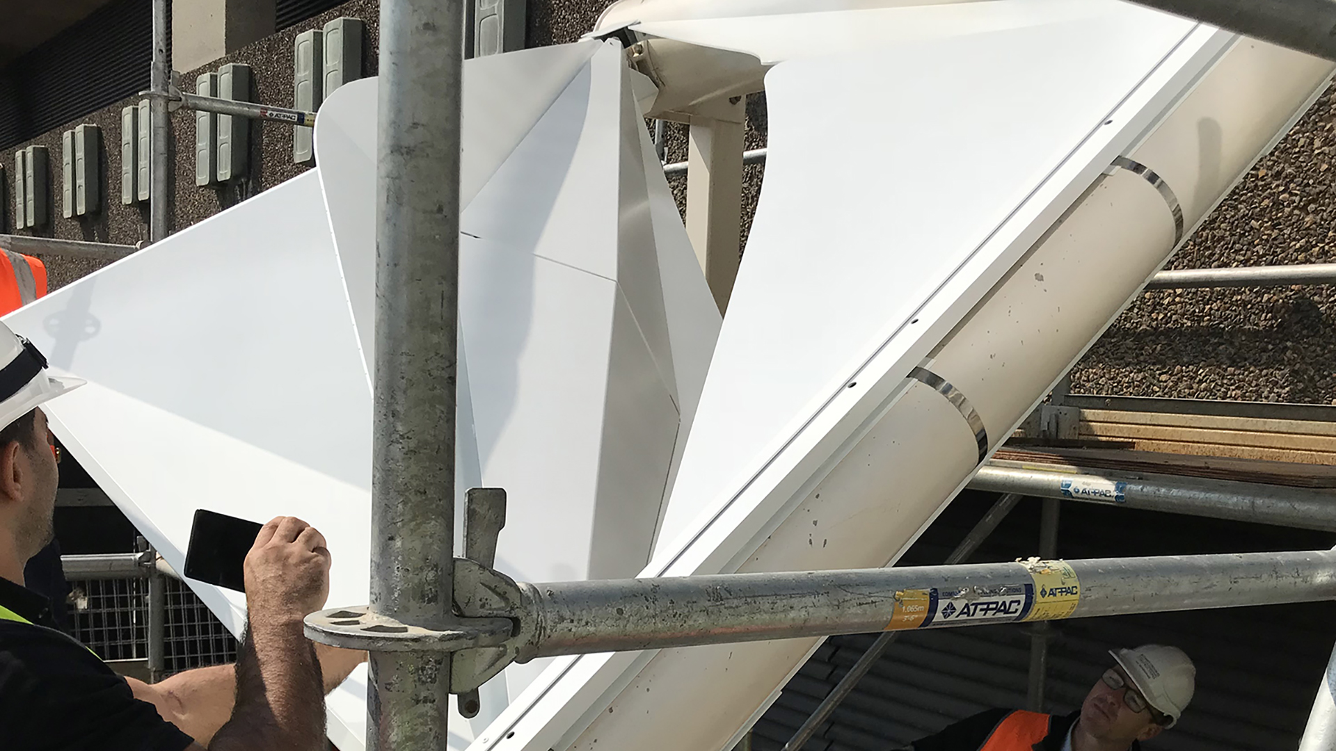
Tip #5: Allow sufficient time for the VMU to be produced manually.

Delivery
Modular code
As John Donne famously proclaimed, no man is an island. Creating a single, large, interwoven script is difficult to troubleshoot and highly problematic when working in teams. Creating clusters may make computation slower, but it ensures a disciplined approach to writing modular code that is legible, easy to troubleshoot, and enables co-authoring. Each cluster should do one thing and one thing only.
Tip #6: Create one cluster per element type.
Continuous Delivery
It is essential to establish a Continuous Integration/Continuous Delivery (CI/CD) digital pipeline right from the outset. Even if the geometry is still a work in progress, objects should be allocated to the correct layer and have all the necessary attributes, such as a unique ID, assigned and ready to use once baked. Rhino 8 makes this super easy with its pass-through components. To avoid information overload, right-click on the pass-through components and select ‘Hide unused parameters’ to hide any unused inputs/outputs.

Tip #7: Set up your cache (aka bake) components from the outset.
Progress updates
Many beginners worry that showing something unfinished will lead to negative judgment. However, showing no output until the very last moment is a recipe for disaster. Even in an imperfect state, daily updates help the broader project team visualise progress, which is critical, as without any tangible output, they will likely grow increasingly concerned until they say, “model it manually”. As they say, done is better than perfect. Baking the model daily shows progress and ensures the CI/CD pipeline is working as expected.
Tip #8: Bake the model daily.
Model updates
To prevent creating duplicate elements when re-baking, use a cache name. Be sure to carefully consider the method you use – purge, push, pull, or bake – as, unlike the Elefront plug-in, once baked, the cache metadata is not visible via the Rhino user interface and cannot be easily modified.
Tip #9: Use a cache name to prevent duplicates.
Version control
Just like a conventional BIM workflow, it is essential to consider how elements should be updated if they have already been issued. This requirement is particularly important when automating sequential numbering, whether for parts or sheet numbers. For example, consider a door schedule. If the door schedule has already been issued and a door is added/removed, the other doors should retain their original IDs. If not, a whole new door schedule would need to be created, causing confusion. Any automated numbering system should consider items previously issued and exclude them from the renumbering process.
Tip #10: Add metadata to elements to identify if it has been previous issued.
Quality Assurance
Just because something is automated doesn’t mean it is error-free. Quality Assurance (QA) is still needed, and while the script will vary from project to project, checks may include: Surfaces are planar; Open breps (when closed breps are required); problematic geometry, such as non-manifold geometry; and missing metadata. Additionally, if you are referencing linework, such as grids, it is a good idea to ensure it is accurate, including being orthogonal.
Tip #11: Create a separate script to audit both input and output geometry.
Approval process
If a project requires a digital fabrication model, it likely involves complex geometry that cannot be easily defined through 2D shop drawings. It makes sense, therefore, that the approval process is undertaken via the model, not the drawings. Model-based delivery is the only way that the approver will truly grasp what is proposed. The challenge is that most construction contracts are not set up to accommodate this process. Special approval will be required, but it is in the best interest of all parties to grant it.
Tip #12: Publish the model to a web-based viewer, such as Speckle, to enable others to easily view and comment on the model.


Documentation
Critical dimensions
Within Revit, we typically separate the 3D modelling process from the 2D documentation process. For example, an element is modelled, a view created, and then dimensions and tags are applied within that view. The dimensions are view-specific, meaning that they are only visible in that view. Due to this workflow, drawings take precedence over the model.
However, if we want the industry to move to model-based deliverables, then dimensions should be created in 3D and baked with the model. If dimensioning individual parts at scale, the challenge then is how to associate the dimensions with the element. One approach is to create separate model layers for the dimensions; however, this can become unwieldy. If, however, the dimensions are baked onto a sublayer within a block, then the information is associated with the geometry and can be filtered out as required. For this to occur, the dimensions must be created simultaneously with the block, rather than being applied retrospectively in a separate script. Creating 3D dimensions will speed up your documentation process, and the wider project team will save hours, if not days, when they review the model.
Tip #13: Bake dimensions onto a sublayer to eliminate the need for manual measuring.
Spot elevations
In Revit, spot elevations can be easily created. However, in Rhino, there is minimal functionality. Points can be evaluated (Analyse > Point), but this will result in static XYZ coordinates, meaning that if the leader is moved, it will not update dynamically. Any static dimension is prone to error and should be avoided. Alternatively, we can use a PointCoordinate Text field. The limitation of this method is that it must reference a point object; it cannot reference the leader location. This limitation means that you must manage two objects—the point and the leader—which is cumbersome. As a workaround, however, a leader and a point can be grouped. It can then be copied around, and the new leader will reference the group point, not the original point.
Tip #14: Use text fields to create dynamic text.
Rhino template
For operational effectiveness, it is recommended that you start with a robust Rhino template. The template should include:
- Document text. These attributes are project information that won’t change from sheet to sheet, such as Project name, Project address, and Project number.
- Layout user text. These are sheet properties that will change from sheet to sheet, such as Sheet number, Sheet name, and Revision. Note that these fields need to be created per layout.
- Title blocks. These blocks should reference the document text and layout user text created above. Note that the title block fields will not be populated unless the layout user text has been added to the layout.
- SetDimensionLayer [Optional]. This setting ensures all dimensions will be assigned to a specified layer, regardless of the active layer on which they were created.
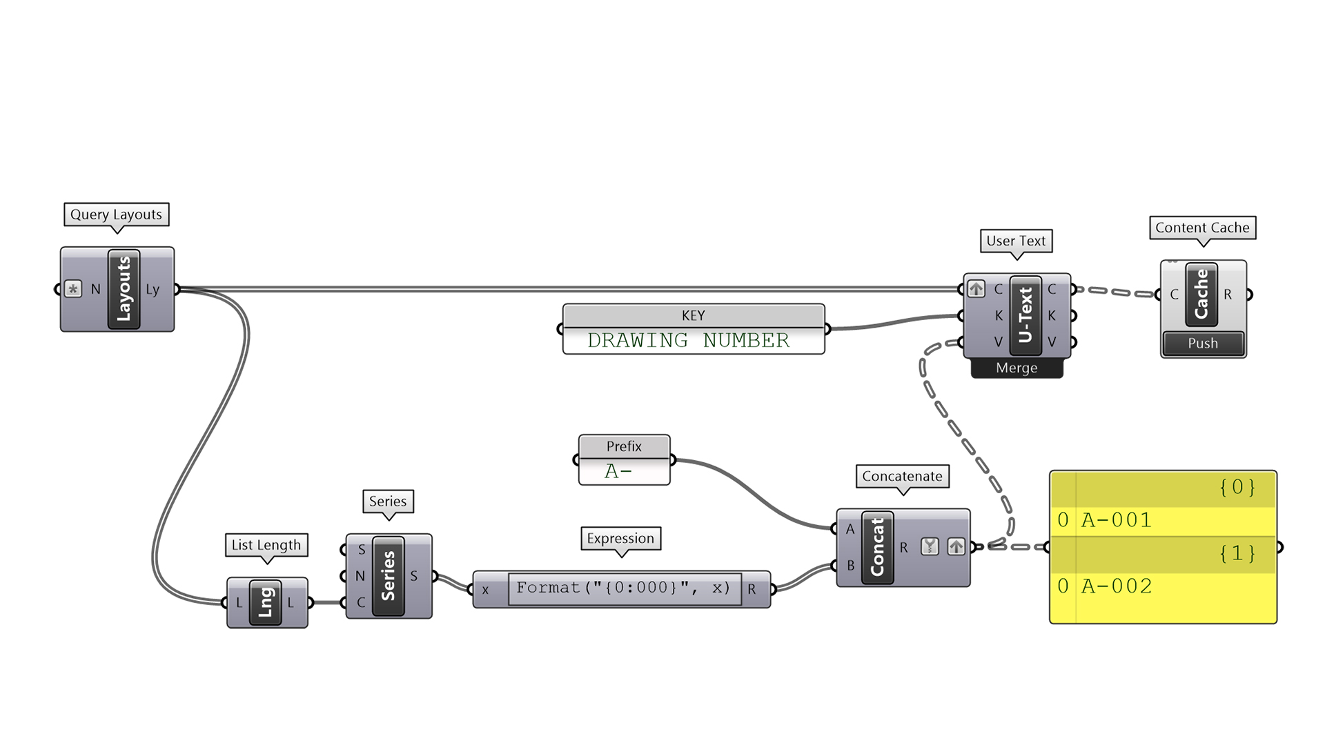
Tip #15: Use out-of-the-box (OOTB) components to read/write layout user text.
Drawings
Before producing any drawings, consider whether they are truly necessary. This statement may sound absurd given the prevalence of drawings in the AEC industry, but when adopting a digital fabrication workflow, it is entirely achievable. As mentioned above, the digital model can be used for approval, eliminating the need for shop drawings. Individual fabrication tickets are primarily used for QA/QC after the part has been fabricated from the digital file. But there are other ways QA/QC can be undertaken without drawings. Often, the only drawings needed are simple base-layer exports for 2D part nesting. Of course, every project will be different, but producing drawings —even if automatically generated —is a time-consuming process.
Tip #16: Question if drawings are really required, given that parts will be digitally fabricated.
Nesting
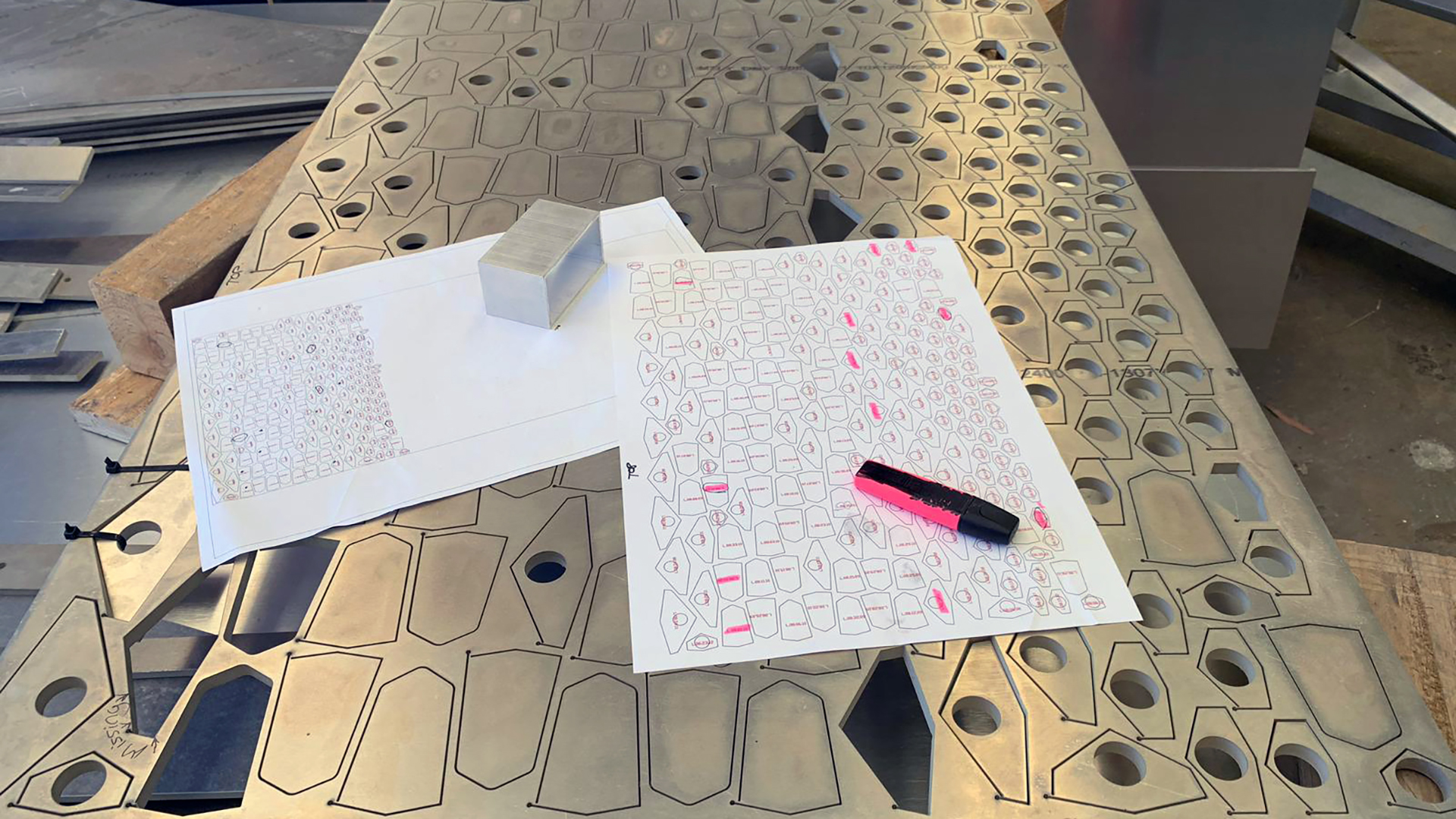
One of the key drawings required for digital fabrication is a detailed drawing of the nested part, which helps reduce material waste. The nesting can be achieved in Grasshopper with plugins such as OpenNest or in Rhino with RhinoCAM. However, before producing the drawing, check with the manufacturer, as they often have their own nesting software and usually prefer to undertake this process themselves. Either way, there are certain things to consider when nesting.
The first consideration is that no one wants a jigsaw puzzle to resolve on-site. Parts should be inscribed with their unique ID, assuming it is not visible —a relatively straightforward process if every part already has metadata assigned. The second consideration is that it is often preferable not to have hundreds of separate pieces, as they become difficult to transport and finding the correct piece becomes a nightmare. One solution is to not entirely cut parts and simply ‘pop’ them out as and when needed. Note that this will require adjusting the part outline to prevent it from being cleanly cut by the CNC machine.

Tip #17: Use the Extend Curve component with a negative value to prevent parts from being entirely cut.
Sheet layouts
If sheet layouts are truly necessary, they should be set up intelligently. For creating sheets and detailed views, plug-ins like DraftHorse can be utilised. If the Rhino Package Manager shows DraftHorse as being installed but it doesn’t appear in Grasshopper, try running the ‘SetDotNetRuntime’ command in Rhino and changing it to ‘NETCore’. Restart Rhino, and it should appear in Grasshopper.
Note that Rhino will significantly slow down after about 20 sheets. The recommended maximum number of sheets per file is around 100, after which the file will become too slow to work with. Therefore, just like a BIM model, how the model is broken down should be carefully considered. How many parts will there be, and how will these be documented?
Detail views, also known as viewports, should be ‘locked’ to prevent the detail scale from being accidentally changed. They should also have a name property. Both of these requirements will enable view titles to dynamically update (unless they are a block) by referencing the detailed view’s properties.
When printing layouts, be aware that Rhino’s display modes are machine-specific, not file-specific, which can lead to inconsistent outputs when multiple team members print layouts. For example, if one team member sets up a custom display mode, that setting is saved only on their machine. To maintain graphic consistency, it must be exported so that other users can import it. While this can be managed, it is far from an ideal workflow. In Revit, for example, all visibility graphic settings are saved in the file, ensuring consistency regardless of who prints it.
Tip #18: Carefully consider how many sheets will be required per Rhino model.
Schedules
Rhino lacks scheduling functionality, which is problematic for projects with numerous parts. However, there are a few workarounds. The first option is to use Grasshopper to generate a schedule and bake the text into the model. The process is quite tedious, as you’ll need to draw the actual table with rows and columns, as well as the schedule text. But this is your best bet if the schedule needs to be placed on a sheet.
The second option is to use Grasshopper to extract the data and export it to Excel. This method can be achieved either by streaming data to a CSV file via a panel component or using a third-party plug, such as Lunchbox or TT Toolbox. This method, therefore, relies on the schedule being a separate document from the drawings. The drawback of this method is that all the data will be overwritten each time it is re-exported.
The third, and preferred option, is to use an external database such as Airtable. The undeniable benefit of this approach is that databases are better for large datasets and can be relational. For example, the part list can be linked to the program schedule, which can, in turn, be linked to the project directory of team members. Data, therefore, becomes structured and easier to manage. Plugins like Mallard allow you to read and write data to Airtable. Best of all, you can edit only the records and fields needed, all with the revision history recorded in the cloud.
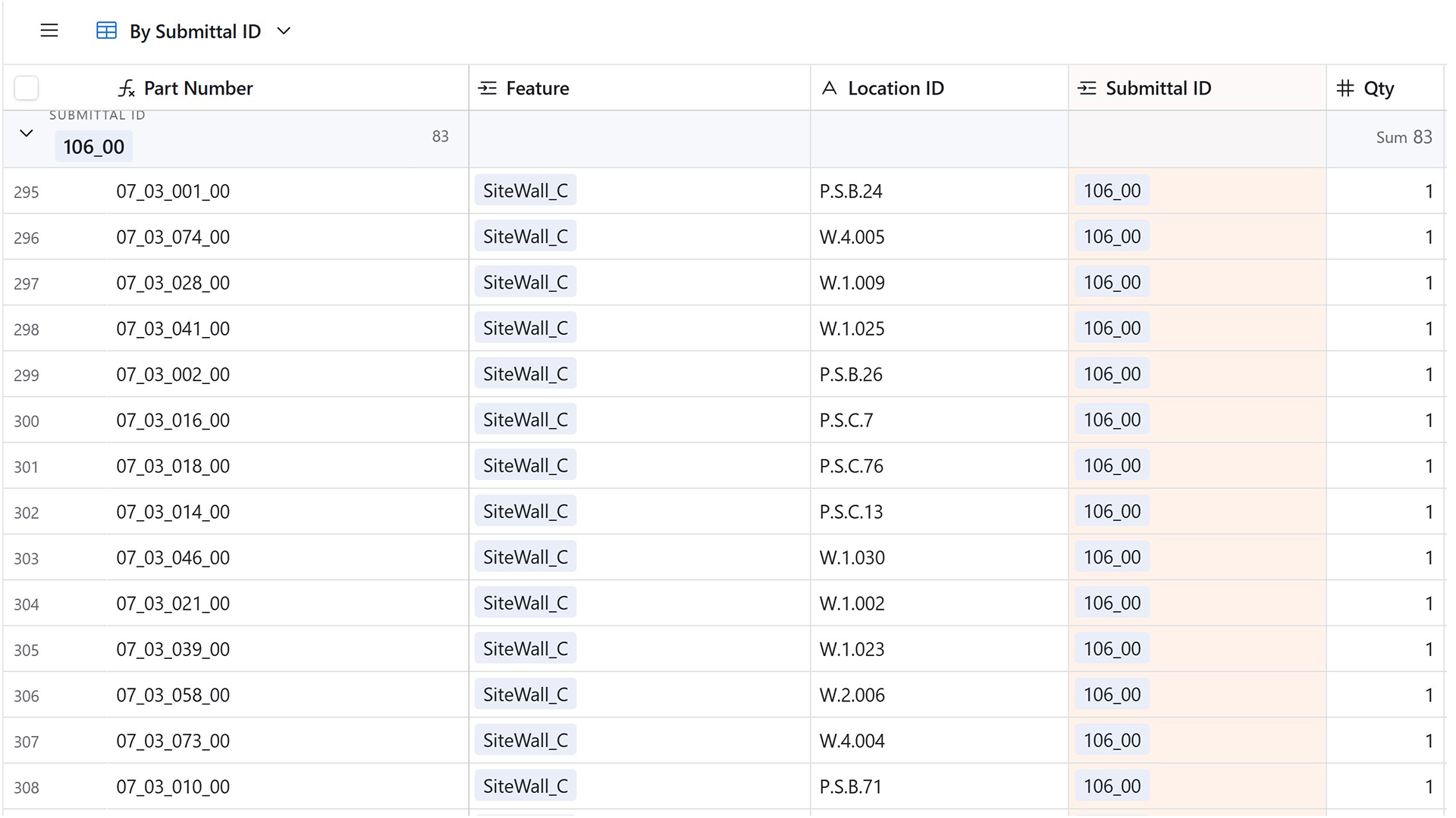

Tip #19: Before pushing data to Airtable, ensure all the Field Names have already been created.
Clean linework
Not all models are created equal. The same applies to drawings. Two drawings can look identical, but how they were made can significantly impact the fabrication process. For example, a curve with excessive vertices will cause a CNC machine to run significantly slower. This problem can be easily resolved in the Grasshopper script by including the Simplify curve component before baking. Similarly, if cut angles are slightly off, say 89.99 degrees, the CNC machine can crash. Auditing the linework, therefore, becomes critical. Keep in mind, too, that toolpath linework may need to be modified to ensure a cleaner fabrication process.
Tip #20: If score marks extend to the perimeter, extend them beyond the part to ensure a clean cut.
2D part export
Most manufacturers will want files other than *3dm (Rhino) files. This requirement means that the Rhino geometry must be exported to some other format. For example, a water jet cutter will likely want 2D parts in *dxf or *dwg format. Rhino offers many different options for exporting linework to *dwg, but if the wrong setting is accidentally chosen, curve geometry will be exported as a faceted polyline. Care, therefore, needs to be taken during the export process, even if the Grasshopper output is correct.

Tip #21: Check the exported file to ensure that the geometry hasn’t been accidentally modified.
3D part export
While some parts will require a 2D drawing for fabrication, others will require a 3D model. However, just like the 2D parts, more often than not, the Rhino geometry must be exported to some other format, typically STEP (*stp). Additionally, the fabricator will likely want each part as a separate file, located at the model origin. Therefore, every part in the Rhino model will need to be repositioned and exported as a separate file.
If the parts have been created in situ, the origin plane must be geometrically calculated, and then the parts repositioned using the Orient command. This process becomes much simpler if the part is a block (with a logical insertion plane), as blocks can simply be instantiated at the World XY plane. Once repositioned in Grasshopper, plug-ins such as Pancake can be used to batch-export parts with a unique filename per part.
Tip #22: Reference the baked Rhino elements rather than the Grasshopper elements to ensure any manual modifications are included in the export.
Manufacturing
Timber grain direction
All timber has a grain direction and is therefore anisotropic. The fibres running end to end are the long grain, and the distance across them the short (or cross) grain. Parts made from timber need to factor in the grain direction to achieve clean cuts, but also from a visual perspective to ensure visual continuity. The alignment of the grain, therefore, must be considered when generating the minimal bounding box of parts for CNC milling. For simple parts, this is a trivial issue. However, for more complex parts, such as a handrail, it becomes more critical.

Tip #23: Establish a plane for each part so that it can be easily remapped to the origin point for the bounding box to be created.
Bending timber
Timber generally comes in a planar form, such as sheets of plywood or rectangular planks. However, this doesn’t mean that they can’t be bent. Various techniques exist to bend timber. For example, steam bending is a technique that softens the timber with steam, allowing it to be bent into the desired curve. Similarly, kerfing uses a series of relief cuts on the back face to enable the timber to bend without breaking. The documentation of the part will therefore depend on the technique used.
If steam bending is used, a jig will likely be needed to hold the parts in place while they cool. This jig will need to be designed and fabricated, and highlights a key concept in complex geometry: what is not built is often more important than what is built. Without the temporary structure, the final structure can’t be built.
If kerfing is used, the in-situ curved panels will need to be unrolled into their planar form, and the relief cuts will need to be documented. Note that kerfing is more art than science, and the sub-contractor will need to experiment with spacing and depth of cuts to achieve the desired curvature.
Tip #24: For breps, extract the finished face surface and use the unroll surface component. For profiled shapes, extract the profile curve and unroll using the Flow component.
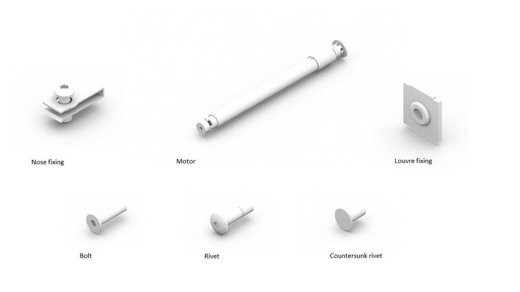
Mass timber fixtures
Contrary to popular belief, mass timber structures contain a significant amount of metal in the form of fixtures, such as screws and plates. Each of these fixtures will require holes, and it is best practice to pre-drill these holes to prevent splitting and facilitate quick assembly. These holes should therefore be included in the digital model to enable CNC machining.
However, before fabrication can begin, shop drawings/models need to be reviewed and approved by the project team. For example, the structural engineer will want to verify the embedment lengths of each fixture. If the digital model only shows the pre-drilled hole, calculating the embedment lengths is complicated because screws often connect two parts, requiring the sum of the hole depths to be calculated. Additionally, pre-drilled holes serve as an installation aid only and are not typically full-length. For this reason, it is critical to model both the hole and the centreline geometry of all fixings.
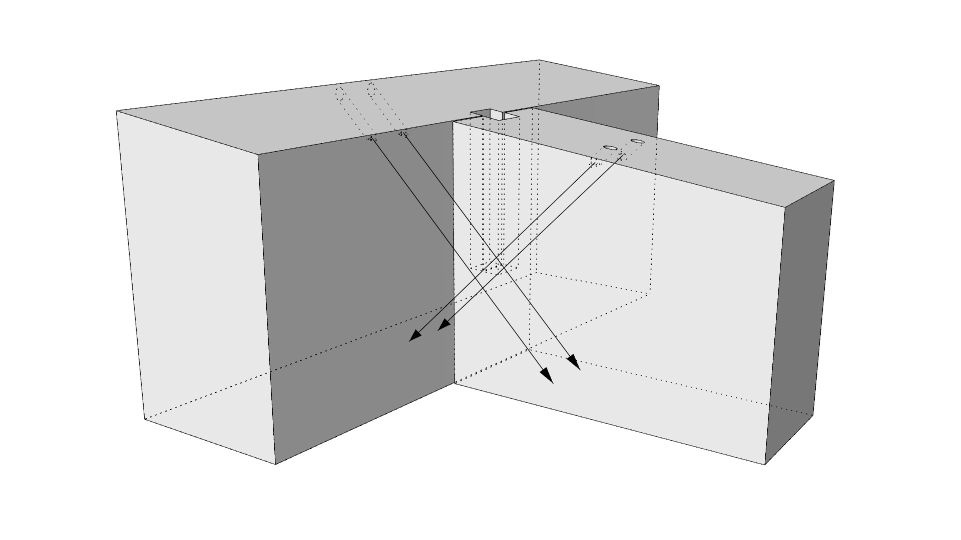
Tip #25: Include the centreline of all fixings, ideally with a ‘decoration’ to display their installation direction.
Transportation
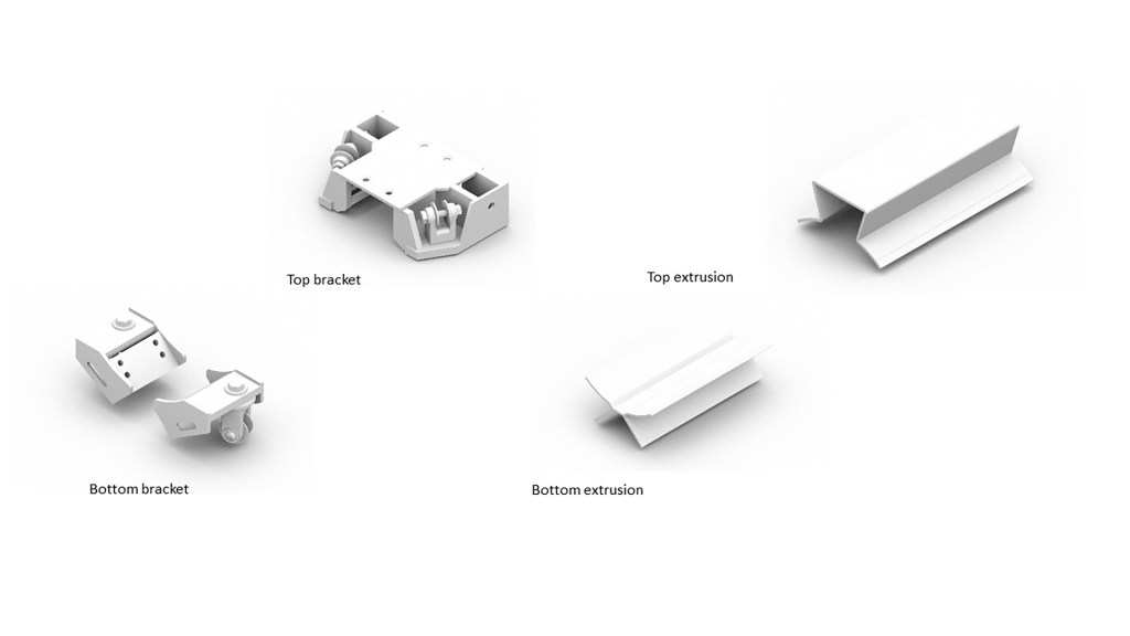
To prevent breakage, parts will typically include temporary elements that are removed once on-site. For example, a mass timber wall with a doorway cutout may be manufactured with the bottom portion of the opening in place to prevent the wall twisting and breaking during transport and installation. This temporary prop is then removed once the part is installed. For these reasons, it may be necessary to show the various lifecycle stages of each part.
Tip #26: Represent the part’s product lifecycle by creating nested layers in the block for each state.
Sheet metal unfolding
Steel metal elements, such as air conditioning ducts, are typically modelled in situ. However, to fabricate it, the sheet must be in its unfolded form. The problem arises because, during the unfolding and folding process, the sheet metal’s shape deforms. This deformation can be calculated using the k-factor, which is the ratio of the metal’s thickness to the neutral axis. The neutral axis is an invisible line that divides the thickness of the metal in half and represents the material that remains unchanged during the bending process. The k-factor utilises this relationship between the neutral axis and the thickness to determine how much the metal on the inside of the bend will compress and how much the metal on the outside of the bend will expand, thereby changing the overall length of the part.
Manufacturing-specific software, such as Inventor or Solidworks, has built-in functionality to develop sheet metal flat patterns with bend allowances. Rhino and Grasshopper, on the other hand, do not have this in-built functionality, as the underlying B-rep unfold operation is a simple geometric process. Pufferfish’s Unrolled polysurface and TT Toolbox’s Unfold components are examples of this. If this process is undertaken, a comparative analysis should be conducted to ensure that any discrepancy falls within tolerance. Alternatively, new plug-ins, such as SheepMetal, enable B-reps to be unfolded with bend allowances.
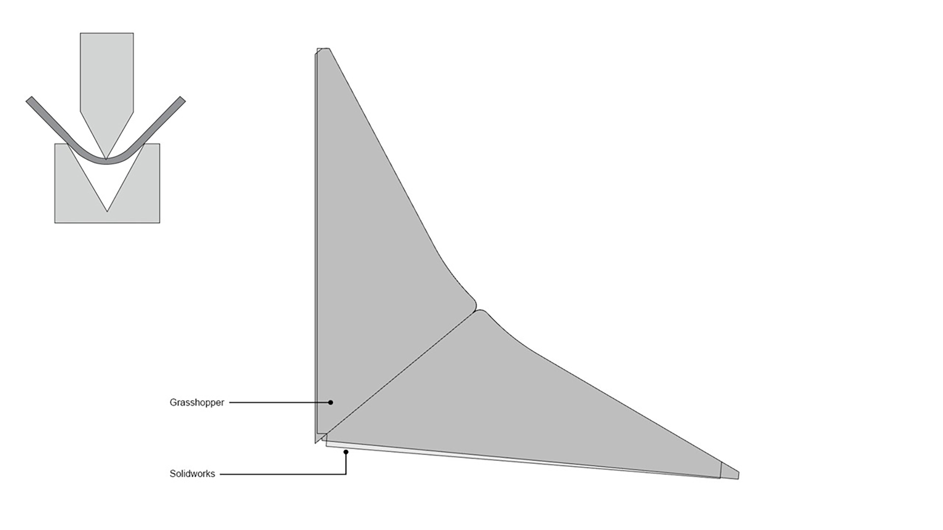
Tip #27: Ensure that all trimmed surfaces are shrunk before unfolding.
Sheet metal folding
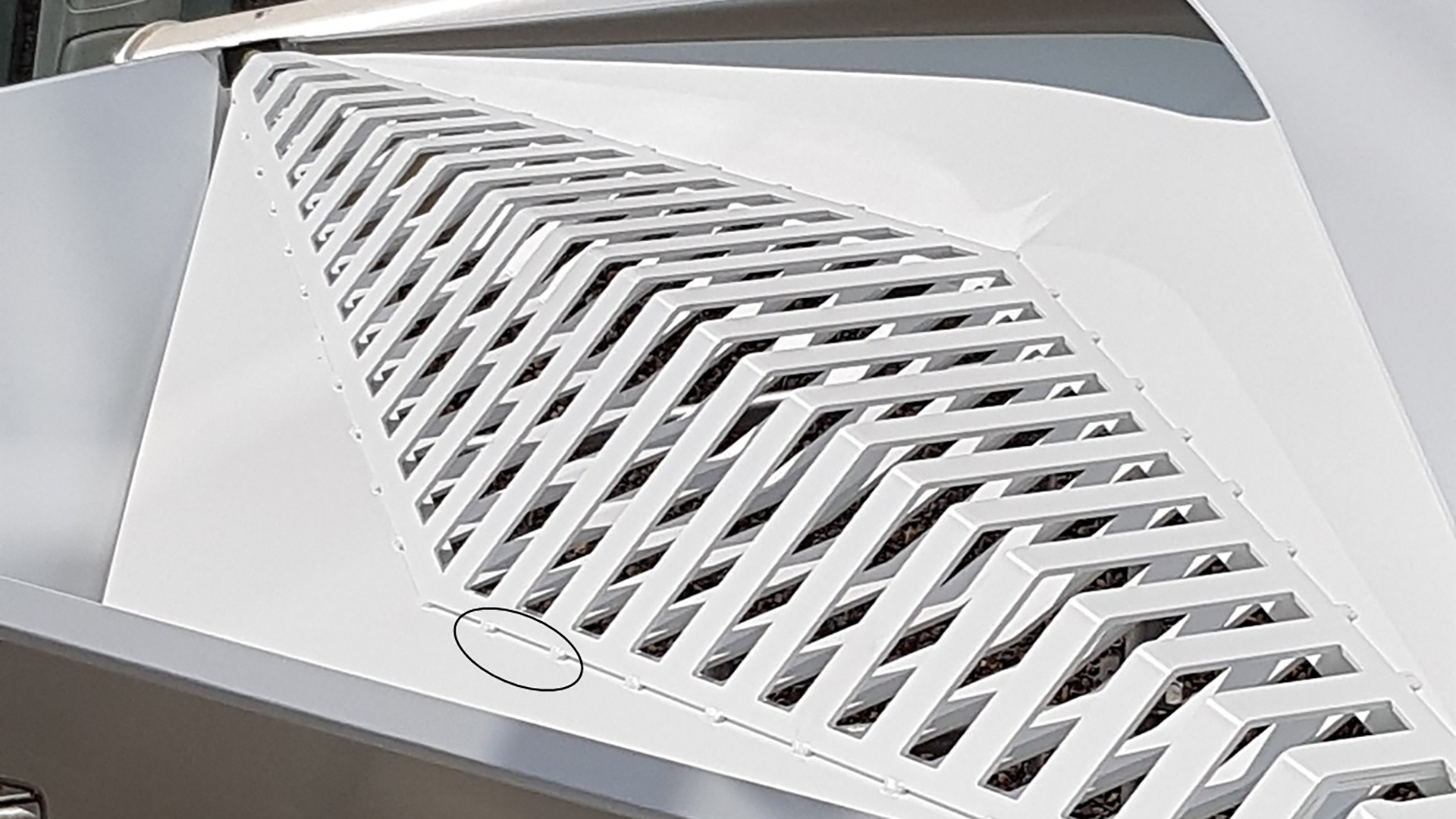
Sheet metal is folded using a press brake machine, where the sheet is positioned between the punch (upper tool) and the die (lower tool). The piece is then held in place by the backstop. However, this assumes that one edge of the part is parallel with the crease. For complex geometry, this may not be the case and will therefore require two people to position the piece manually. To assist in positioning, score marks should be used at the end of the crease line.
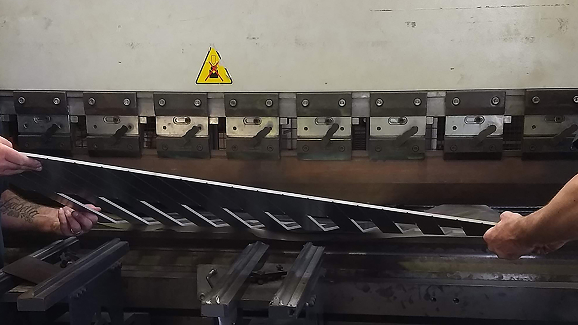
Tip #28: Create score marks at crease lines to assist in aligning the part for folding.
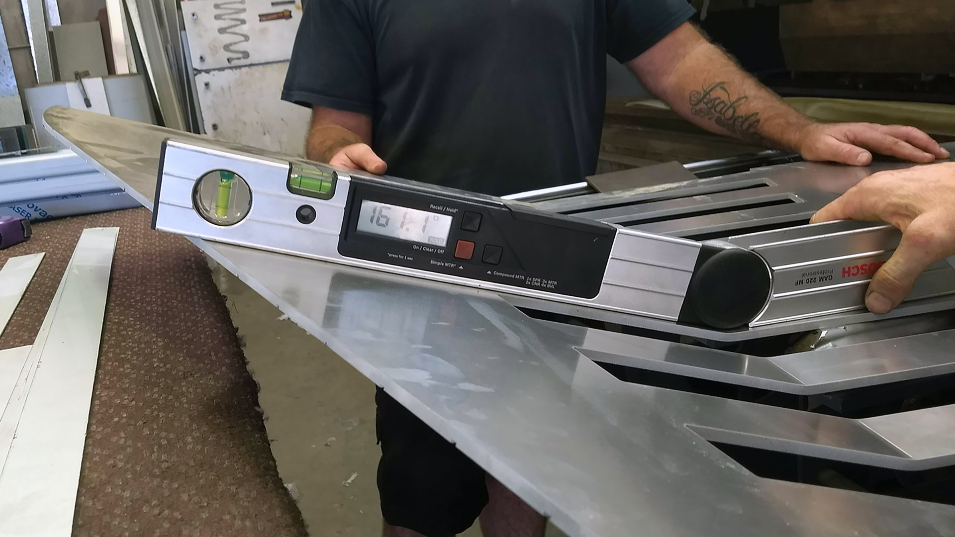
Aluminium bend angle
Beyond a certain threshold, the outer surface of a fold can fracture. To prevent this, generate a Grasshopper script to audit all the fold angles in the project and compare them against the maximum fold angle allowed for that particular grade of aluminium. Parts that exceed the maximum bend allowance should be colour-coded for review.
Tip #29: Include material limitations checks, such as maximum dimensions, in a geometry audit script.
Welding
Welding involves melting two pieces, often with a filler material, to join them into a single piece. However, one key concept of DfMA is to make fabrication and installation as simple as possible. Unfortunately, welding is often manual and labour-intensive and should be avoided.
If welding cannot be avoided and it will be visually prominent, then how the parts are welded should be carefully considered. The best way to resolve this is via a series of prototypes to test the size and spacing of the welds. To maintain control of the manual welding process, it may be desirable to embed fabrication ‘intelligence’ into the part, such as by adding a recess, so the welder knows precisely where the welds start and stop.
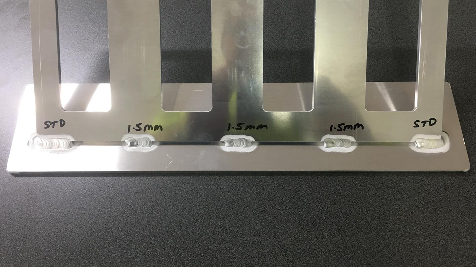


Tip #30: Add recesses where welds are required to control the manual welding process.
Conclusion
Like most things in life, digital fabrication must begin with the end in mind. What material are you using? How will it be manufactured? What are the limitations of the materials and machinery? How will it be installed? While each project and material will have different requirements, the key concepts remain unchanged: detail versus accuracy, instances versus types, Design for Manufacture and Assembly, and the digital pipeline. By religiously committing to these concepts and adopting the best-practice tips provided, you are setting your project up for success. Best of all, you will be employing design-to-fabrication workflows that enable faster construction, minimise resource use, and produce material-specific design solutions.
If you are interested in learning more about how Parametric Monkey can help your project, please get in touch via our website.
References
1 Doctored image from Open Systems Lab. (May 2019). The DfMA housing manual.


1 Comment
Kerry Thompson Kerry Thompson
Thanks, Paul, for such a thorough and insightful guide.
I particularly appreciate your attention to detail and accuracy. It’s one of the rare instances where I’ve seen Revit’s limitations in terms of fidelity addressed so clearly. As someone who has been using AutoCAD to draw and create 3D object models since 1986, this has always been a point of frustration when working with Revit.
Revit’s approach to system families as monolithic forms, supplemented with drawing elements, also presents certain limitations. Additionally, the complexity and inefficiency of Revit’s loadable families make it challenging to create detailed models suitable for driving fabrication systems.
In many respects, Revit feels like the “Minecraft” of BIM—it has yet to fully realise the potential that CAD and modelling systems from the pre-2000 era set the foundation for.
The way things are going, this may never happen, as AI-based solutions may displace it in the medium to long term.
Kerry Thompson