

Often, when producing a SEPP65 solar access analysis, you will want to generate 3D views from the sun to visually verify the results of the Ladybug ‘heatmap’. To solve this issue, Parametric Monkey has developed a Dynamo graph, available as part of our Dynamo Package Development service, that generates views directly in Revit. (To see how this can be done within Rhino.Inside Revit, refer to our Rhino.Inside Revit views from sun tutorial instead).
Location settings
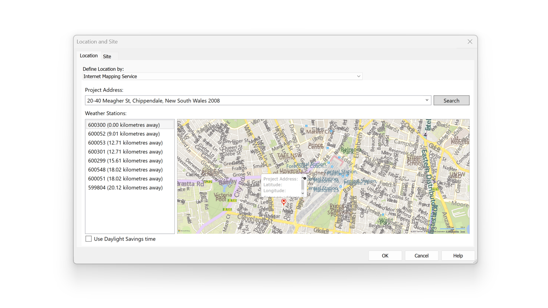
Before running the script, ensure that the Project Location (Manage > Project Location > Location) has been set and that ‘use Daylight Savings Time’ is disabled. This is important, as Revit’s inbuilt Daylight Savings Time (DST) settings will modify the solar vectors by one hour for all times, regardless of the actual DST range for that location.
Sun settings
Next, in the active view, set the desired sun settings. The Dynamo graph will reference these settings to generate the new 3D view. For example, a single-day solar study, from 9:00 a.m. to 3:00 p.m. with a time interval of 15 minutes, will return 25 views. Note that the times should represent solar time and exclude Daylight Savings Time.

True North
It doesn’t matter if the view’s orientation is set to Revit’s True North or Project North. However, to ensure accuracy, the model must be orientated to the real True North, that is, the direction along the earth’s surface towards the geographic North Pole, and not Grid North, such as GDA2020_MGA56. If your Revit model references Grid North, consider setting up a new ‘container’ model with the correct orientation to True North and run the Dynamo graph in that model.
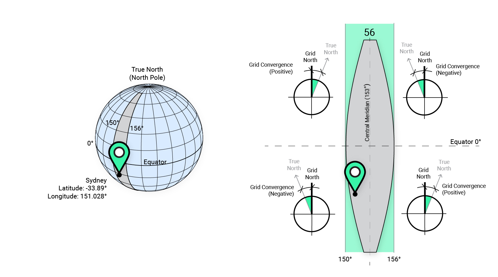
The difference between True North and Grid North is known as Grid Convergence, and it varies depending on your location and grid projection. Sydney, for example, has a latitude of -33.89° which means it is in the Southern Hemisphere and has a longitude of 151.028°, which means it is located to the West of the Central Meridian (153°) in MGA zone 56. This means that True North is West of Grid North, with an angle of approximately -1°. If your survey doesn’t contain this information, many government agencies publish Geodetic Calculators to assist in calculating the grid convergence.
Dynamo workflow
To run the graph:
- Define an optional view name prefix (#1).
- Define the date format (#2). The formatting is based on standard Microsoft date/time conventions.
- Define if the sun path should be enabled (#3). This can be useful in visually confirming the view orientation.
- Define is the 3D view should be locked (#4). This setting will prevent any accidental orbiting of the view.
- Define the shadow intensity percentage (#5).
- Press Run.

Computational logic
The graph extracts the sun settings from the active view and calculates the sun vectors. By default, the DateTime is returned relative to Coordinated Universal Time (UTC) +00:00. To reference these values for the view naming convention, the DateTime is amended to factor in the time zone, which is automatically calculated when defining the location of the project (Manage > Project Location > Location). For example, the Australia Eastern Standard Time (AEST) used in Sydney, Australia, is UTC + 10:00 hours. The end result is a naming convention that matches the sun settings.
Next, the project rotation, known as ‘Angle to True North’, is calculated, and the sun vectors are adjusted accordingly. Finally, the axonometric views are created, and the various view properties are set. Each view will have a ‘Still’ sun setting applied that matches the view.
Visual verification
Note that while the sun settings are defined for each view, shadows are not enabled. This is because turning on shadows for views slows down Revit. Also, since the view is aligned with the solar vector, shadows are fully concealed behind the geometry and not visible. However, to visually check that the graph worked as intended, you can temporarily turn on a view’s shadows, unlock the view, and orbit the view slightly to see the shadow.
Conclusion
Setting up axonometric views parallel to sun vectors can significantly assist in visualising which parts of a building receive sun during specific times of the day. Moreover, this is often a requirement for Development Applications. With automated routines such as this one, this process can be performed quickly and accurately.
To learn more about our Dynamo Package Development service, drop us a line and discover how we can automate your Revit workflows.


