
Often when producing a SEPP65 solar access analysis, you will want to generate views from the sun to visually verify the results of a Ladybug ‘heatmap’ analysis. To solve this issue, Parametric Monkey has developed a custom script that generates views directly in Revit. The workflow utilises Rhino.Inside Revit, with the latest Ladybug Tools plug-in. To see how the same can be achieved with Dynamo, check out our views from sun tutorial.
Rhino.Inside Revit
With the release of Rhino.Inside Revit, we can now run Grasshopper directly inside Revit and create native Revit elements. It also means that we can access the extensive third-party plug-ins in the Grasshopper ecosystem, including Ladybug. Back in November 2020, ‘Ladybug Tools’ was released, which contains significant performance and accuracy improvements. As such, our preferred workflow for generating views from the sun is to use Ladybug with Rhino.Inside Revit.
Workflow
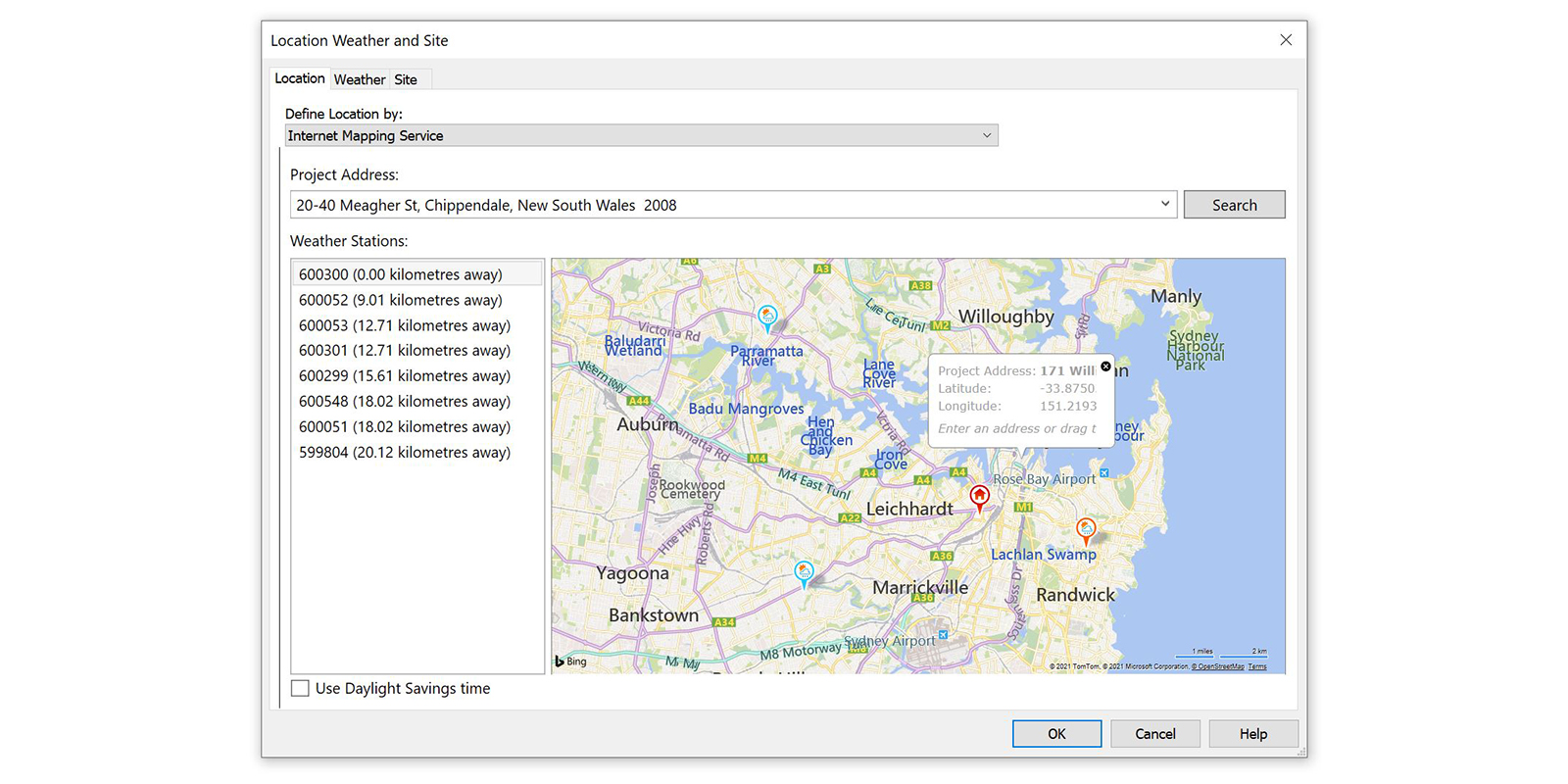
Before running the script, ensure that the Project Location has been set in Revit. Go Manage > Project Location > Location and set the project address. Note that the ‘use Daylight Savings Time’ setting will not affect the script.
To run the script:
- Define the analysis period. Note that the longer the analysis period, the more views that will be created and the longer it will take to run the script
- Define the view name prefix. Views will be named “PREFIX_DAY MONTH TIME”. For example, 3D SOLAR_21 JUN 0900.
- Define the 3D view type name to be applied to the view.
- Define the 3D view template name to be applied to the view.
- Choose if the views are to be locked. Note that if you have previously run the script and set them to be locked, it’s best to first delete the existing views or unlock them.
- Press Run to create the views.

Computational logic
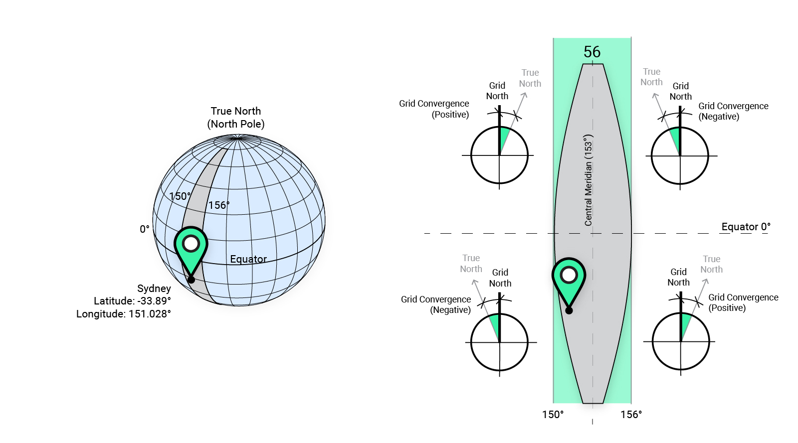
The script collects the Project Site Location and uses its latitude and longitude to create a Ladybug location. Next, the project’s Angle to True North is returned and combined with the grid convergence input to define north for Ladybug. If your Revit model is orientated to the real True North, that is, the direction along the earth’s surface towards the geographic North Pole, then the grid convergence is 0. However, if your Revit model is orientated to Grid North, such as GDA2020_MGA56, you’ll need to factor in grid convergence.
Grid convergence
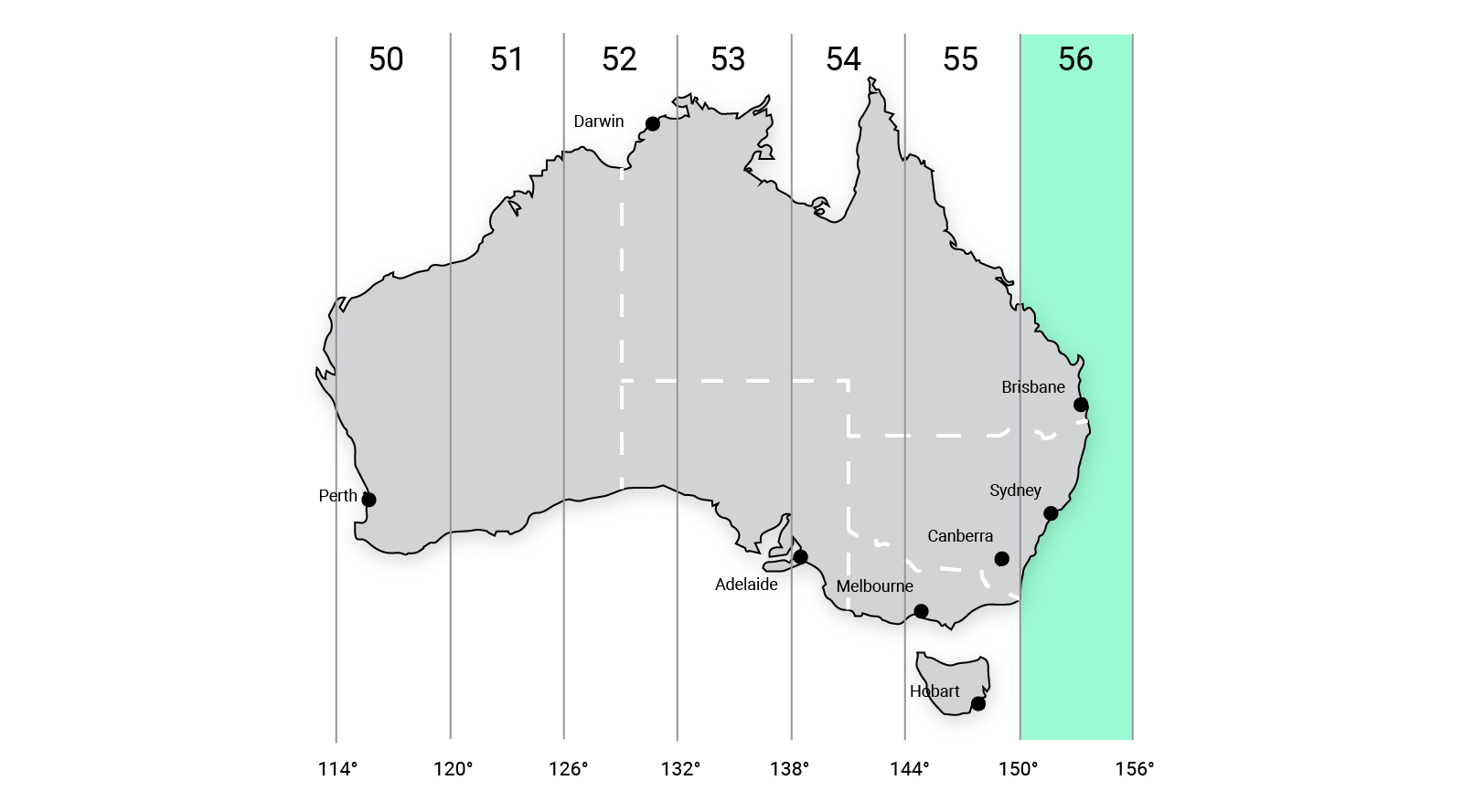
Grid convergence varies depending on the location and can be positive or negative. For the script, negative values indicate True North is to the West of Grid North, while positive values indicate True North to the East of Grid North. Sydney, for example, has a Latitude of -33.89° which means it is in the Southern Hemisphere and a Longitude of 151.028°, which means it is located to the West of the Central Meridian (153°) in MGA zone 56. This means that True North is West of Grid North, with an angle of approximately -1°. If your survey doesn’t contain this information, many government agencies publish Geodetic Calculators to assist in calculating the grid convergence.
Create views
Once True North is known, the script generates sun vectors for the analysis period and creates axonometric views. By default, these views are the default ‘3D View’ type. If, however, an alternative view type is specified, this type will be used instead. If a 3D view template is specified, it too will be applied.

Element tracking
The tracking mode of the views is set to ‘Reconstruct’. This setting means the views will be updated where possible if the script is re-run. However, if the views have been locked, they will first need to be unlocked before re-running the script with different settings; otherwise, an error will be returned.
Visual verification
To verify that the views are parallel to the sun, manually turn on the shadows. If your Revit model is orientated to True North, the shadow’s should not be visible. However, since the algorithm used by Ladybug is based on the U.S. Department of Commerce National Oceanic & Atmospheric Administration (NOAA) solar calculator, it varies slightly from Revit’s in-built algorithm. Consequently, there may be a slight discrepancy in results. Note that if your model is aligned to Grid North, the shadows will be wrong as Revit doesn’t factor in grid convergence.
Conclusion
Setting up axonometric views parallel to sun vectors can significantly assist in visualising which parts of a building receive sun during specific times of the day. Moreover, this is often a requirement for Development Applications. With the assistance of automated routines such as this one, this process can be performed quickly and accurately.
To find out more about this script or our custom software development service, drop us a line and discover how we can automate your workflows.


