
There are various ways in which Rhino geometry can be used within Revit. The most basic method is to export a *sat file from Rhino and then import it into Revit. Best practice is typically to do this via a conceptual mass family. However, the result can be called ‘dumb geometry’ in that it is unable to be edited once imported, which is far from ideal in a BIM environment.
The next progression in usability is to explode the import instance. Depending on the base geometry, Revit may make editing the mass accessible via grips (push/pull arrows), but this is not always the case. However, the best method to generate native Revit elements from Rhino is to use the wall-by-face, roof-by-face, curtain system and/or mass floors commands. These elements will be hosted to the Rhino geometry. In theory, these elements can be updated if the base geometry changes but experience has shown that Revit is not always able to re-discover the host element and new elements will need to be created. Therefore, it is prudent to test the Rhino to Revit workflow before investing in too much time in embellishing the Revit elements.
The whole process of using Rhino geometry in Revit feels a bit like black magic. Often, the first attempt in importing the geometry will fail, and there will be no guidance from Revit as to why it failed. This lack of feedback can prove to be very frustrating, and many users will give up. However, here is a list of best practices to follow when generating the mass in Rhino so that integration with Revit will be smoothness (or at least less painful).
Rule 1: Closed poly-surfaces are less likely to fail
To avoid the ‘mass contains only mesh geometry’ error when importing a conceptual mass family to a project, ensure that there are no naked edges and that the mass is a single brep/poly-surface in the original Rhino model. This exercise can be time-consuming, but it will force you to integrate your model and ensure it is well built.

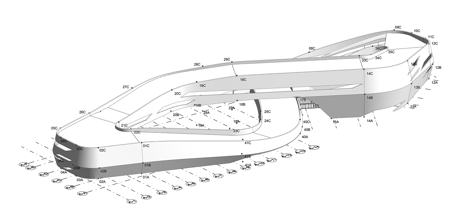
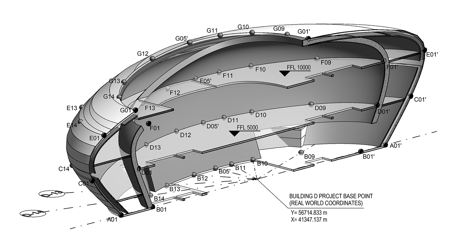
Depending on the complexity, it is also prudent to split up the Rhino model into more manageable pieces for Revit. This recommendation is especially important if trying to use the ‘wall-by-face’ or ‘roof-by-face’ command on complex forms. In the example below, the Rhino model was split into several pieces and exported individually as separate *sat files. This process proved to be much more successful than attempting to import it as one large piece.
Rule 2: Explode the *sat file to test its usability
A good test to see if Revit can handle the complexity of a Rhino mass, is to import the *sat file and see if you can perform a ‘full explode’ (Modify > Import Instance > Explode) on the geometry. If this works, it is more likely that Revit will be able to generate native Revit elements from it. If however, Revit is unable to explode it, you will get the ‘Import contained 3D data or points which can’t be exploded. Only 2D data was exploded’ error message. In this scenario, consider rebuilding the Rhino geometry using sweeps and network curves and re-export. For whatever reason, these tend to be more easily translated than lofts and trimmed surfaces. Note that from Revit 2017 onwards, this feature has been removed.


Rule 3: Keep the number of control points to a minimum
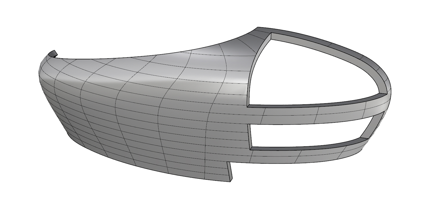
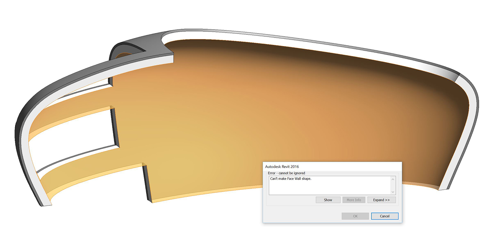
Control points too close together in a Rhino surface will cause errors when trying to use the ‘wall-by-face’ command. The project below required an ellipsoid shaped double wall. The setting-out geometry defined the outer shell. It is quite easy to use the ‘offset surface’ command in Rhino to get the inner wall. However, using this method significantly increases the UV count of the surface.
Thus while it is a bit more tedious, it is better to offset the base curves and rebuild the geometry from scratch. Ideally, the new curves should be rebuilt to have the same properties as the original curve, for example, 40 control points, 3rd-degree curve. If the curve is a spline, the deviation from the initial curve to the new curve will be negligible. If the curve is an arc or ellipse, the number of control points shouldn’t be a problem. While there may be some slight deviation from the desired geometric definition, it should allow you to generate native Revit elements from it.

Rule 4: Split closed NURBS curves
With rare exception, Revit has difficulty creating forms if it is dealing with continuous, closed curves. You’ll notice that when you loft continuous rational forms like circles or ellipses, Revit will automatically produce two surfaces. It is therefore recommended making your curves in Rhino as two segments before bringing them in. This way, you will have full control over the geometry as opposed to letting Revit decide where the split occurs.
The massing below was generated using the ‘sweep 2 rail’ command for each surface. The surfaces were then joined together to create a closed polysurface. The geometry can then be exported as a *sat file and inserted into a Revit conceptual mass family. You’ll notice that without modifying the import instance, Revit automatically splits the closed curves. This automation is not ideal if you want control over where and how the surface is split.


Rule 5: Generate untrimmed surfaces rather than trimming them
Rhino’ remembers’ if a surface is trimmed. To test if a surface is trimmed, the ‘PointsOn’ command can be used. As shown in the image below, the original surface of the right has been trimmed whereas the surface on the left has been built using ‘sweep 2 rails’. (Note, it is also possible to ‘network surface’). While these surface mostly looks the same, they may behave very differently when imported into Revit.

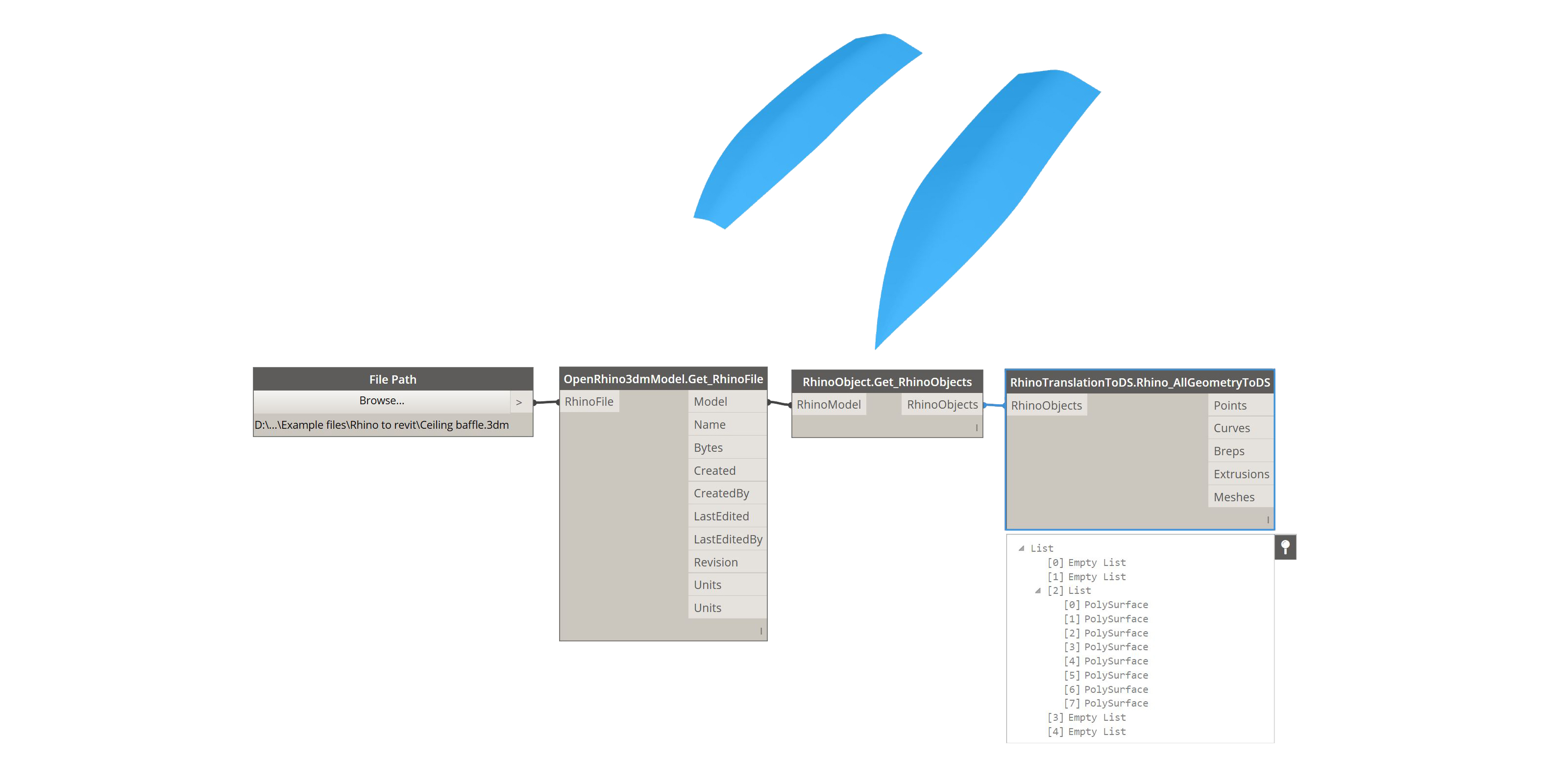
Initially, when I first discovered this issue back in 2013, I was using CASE’s OpenNURBS plug-in, which was developed by Nate Miller. The plug-in was subscription-based and allowed users to import Rhino geometry directly into Revit. It was the precursor to Rhynamo. However, it was discontinued in mid-2015 when WeWork acquired CASE. So is this rule still relevant? The short answer is sort-of. If you plan on using the trimmed surface as a host for a wall-by-face, then you shouldn’t have any problems. If however, you plan on importing the trimmed surface into Dynamo via Rhynamo, then you will encounter the same issue as shown below.
Rule 6: Avoid singularities
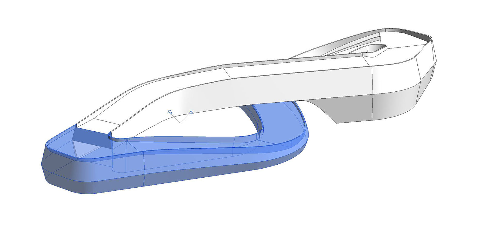
When surfaces taper to a point, this is generally not a problem for creating a mass. However, if you intend to use the mass to generate Revit native elements such as a wall-by-face or a curtain system, it will likely fail. To avoid this, you can either rebuild the surface in another manner or truncate the surface to avoid the singularity. In the example below the surface on the left has been generated using a loft and then trimmed. Whereas the surface on the right was created using a sweep 2 rail. Due to the converging UV grid on the right surface Revit is unable to generate a wall-by-face.


Export
Now that you know how to build your Rhino model so that it won’t fail, here is how to import it into Revit:
- Export Rhino geometry (using origin 0,0,0) to a *sat file
- Created a new conceptual mass family in Revit
- Import *sat geometry
- Save family to your project library location
- Load family into the main building and place component
- Place component onto its workset, for example’ façade mass’
- If creating walls, use the ‘wall by face’ command
- Turn-off component’s workset
- If the geometry needs to be modified, use the Rhino model as the ‘master’ file
- Export a new *sat file and overwrite the geometry in the Revit family.
- Reloaded the conceptual mass family into the project and select overwrite
- Select and hosted geometry (wall by face, roof by face, etc.) and select ‘update to face’.


1 Comment
Mike
This article was helpful but after following all the instructions, I was still getting an error message when I tried placing a roof by face to a conceptual mass created with an SAT export from Rhino.
I wasn’t sure if it was the particular geometry or something else.
Ultimately, I discovered I needed to assign a facia depth to the roof type when I used the two-cut square eave condition.