

This tutorial explores how to create various types of annotations within Revit including tags, dimensions, and keynotes. Visibility of annotations are controlled via the ‘Annotation Categories’ tab of Visibility/Graphics Overrides. Annotations are view specific meaning that you will need to duplicate annotations for each view. It is best practice to use these objects instead of conventional text. This is because while text objects are static, these elements will update dynamically once an element is modified.
Tags
Tags are text labels for elements such as doors, walls, windows, rooms, and several other objects that architects typically need to reference in a set of drawings. These tags usually refer to other schedules or information in other portions of the drawing set. In Revit, tags are intelligent, bidirectional symbols that report information stored in an object’s properties. You can enter a value directly into the family properties or right into the tag itself.
Once you’ve tagged an element and given the tag a value, the element will retain that value until you remove it. The value lives with the elements within Revit; it is not a property of the tag. This structure allows you to delete or remove tags without any fear of losing the data entered into the tag. It also means that once an element is tagged with information in one view, that same element will report that same information in any other view that it is tagged in without you having to have the data entered twice.

When families such as doors and windows are placed into the project, they are automatically assigned a unique Mark number. These are sequentially numbered in the order they were placed.
Tagging elements
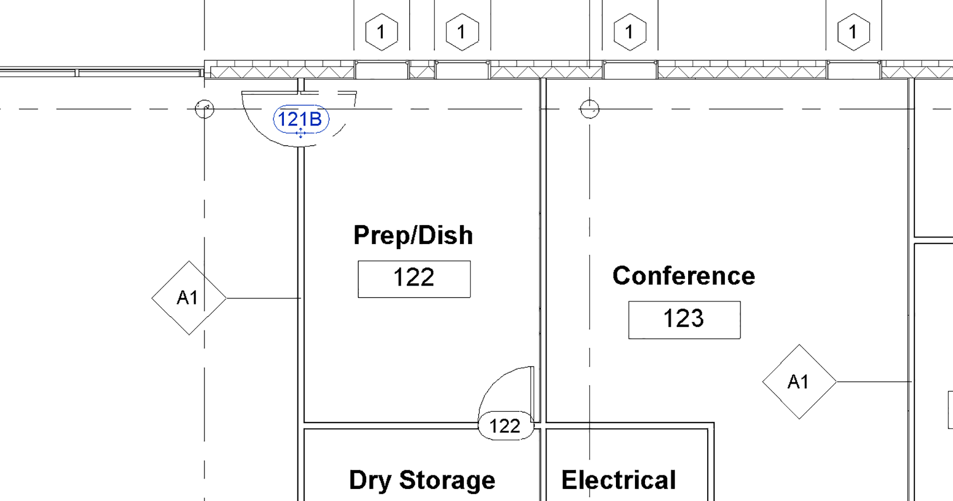
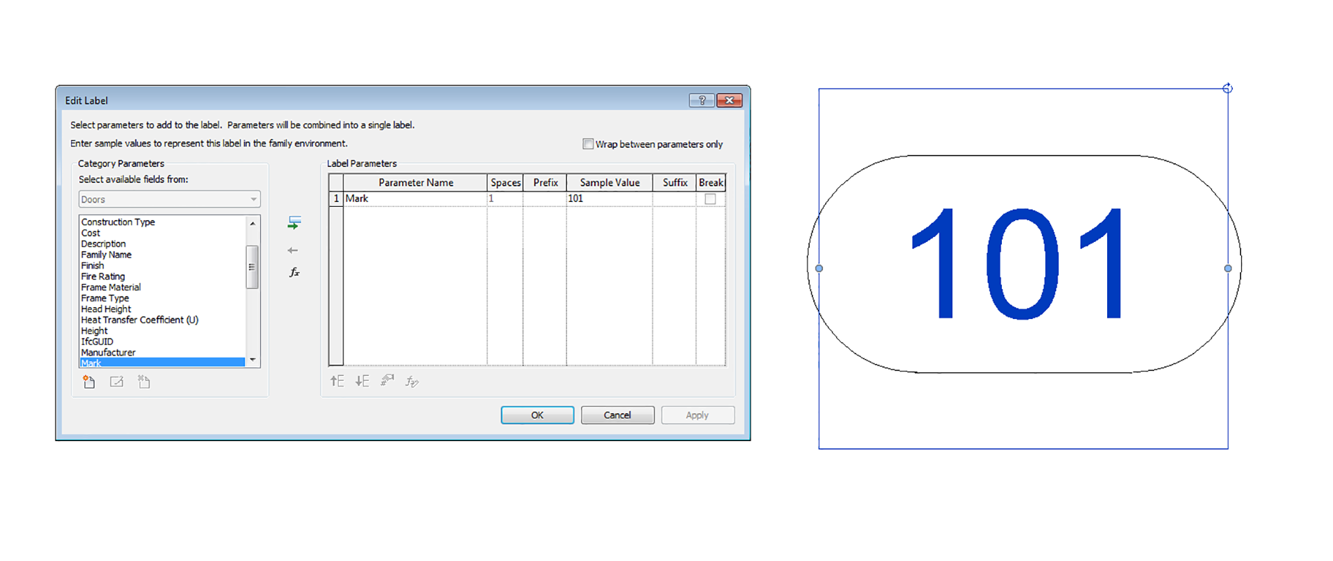
To tag an element such as a door, go Annotate > Tag > Tag by category and select the door. To tag multiple objects at once, you can use the Tag All button, Annotate > Tag > Tag all. Depending on the Door tag family loaded into the project, different information might be shown. However, typically it will be just the Mark value. The family’s mark number can be found in the Properties window. To change the door’s Mark value, you can either change it via the Properties window with the element selected or within a schedule.
Rooms tags
Before you can tag a room you need to make sure a room exists. In Revit, rooms are 3D objects with name and area properties. To add a room, go Architecture > Room & Area > Room. Select the zone you want to add the room. Revit will automatically find the bounding walls. However, be aware that there are multiple ways to calculate a room’s area. To change how Revit calculates the area, go Architecture > Room & Area and hit the arrow to see more options, and select Area and Volume Computations.

Renumbering elements
Elements such as rooms, doors and windows should be numbered logically. For example, typically they will be prefixed with the Level or Room Number it belongs to, as well as being numbered clockwise. Refer to this tutorial for automating the process of renumbering rooms.
Dimensions
Dimensions are used to convey the distance or angle between elements or parts of elements. In Revit, a dimension is a bidirectional annotation that essentially tags distance or size. This function means that you can edit the distance directly within the dimension string to move elements to a specific distance apart; likewise, the dimension updates automatically as the distance between elements changes.
Like all annotations in Revit, dimensions adjust to the scale of the drawing. They will always appear at the proper scale in the view. If you change the view scale, the dimensions automatically resize.

By default, a linear string of dimensions only dimensions parallel entities. Nonparallel elements, by their very nature, have a dynamic dimensional relationship. Dimensions in Revit always read from the bottom or the right following the standard architectural sheet layout conventions. To place a dimension, choose any dimension tool and begin selecting entities in a sequence. You can keep selecting multiple objects in a given direction, creating a dimension string across your drawing.
Once the dimensions are placed, you can relocate them by selecting the dimension and grabbing the blue grips. By selecting and holding this element, you can move the witness line to a new host element without having to recreate the entire dimension string.

Ensure that you only annotate what’s in your scope of work. For example, don’t indicate structural sizes. Instead have a general note saying ‘Refer structural drawings’. The contractor should read all sets of documents in conjunction. By going beyond your scope of work, you are opening yourself up to liability.
Keynotes
Keynotes are a means of annotating model elements. Rather than merely being discrete strings of text used to label things, they are a family or class of objects linked to model elements. This function means that each instance of annotation will always be associated with the same object and that if one instance is changed, so will all the others.
In this way, annotations do not have to be typed over and over again. Instead, keynotes are defined in a tab-delimited text file and linked to the relevant objects using the keynoting tool included in the BIM software. For the same reason, keynote text cannot be edited where it appears – it has to be modified in the keynote *txt file.

Keynote codes can be entered directly in the keynote parameter field of the Family Type dialogue box. However, it is generally easier to use the keynote *txt file, where all keynotes can be seen as a group. If the keynote in the text file is different from the one already entered in the dialogue box, the keynoting tool will overwrite the one in the dialogue box if it is used on that object. Keynotes are generally associated with a country’s specification system. For example, in the UK, the National Building Specification (NBS) is used to describe the materials, standards and quality of a construction project. In Australia, NATSPEC is used.
Schedules
Schedules are technically a view, not an annotation. However, they are important as both a Quality Assurance (QA) check and also as a documentation system. Typical schedules include doors, windows, walls, furniture and equipment. To create a schedule:
- Go to the Project Browser, right-click on Schedule/Quantities > New Schedule/Quantities. Alternatively go View > Create > Schedules > Schedule/Quantities.
- Select the category, e.g. Doors.
- In the fields list, select the desired fields and click Add. Typical fields include Level, Mark, Width, Height, Fire Rating and Family and Type.
- Under the Sorting/Grouping tab, set sort by to Level, and check the Header and Blank line boxes.
- Still within the Sorting/Grouping tab, set the ‘Then By’ to Mark.
- Under the Formatting tab, select the Level field and check the Hidden field box. This setting ensures the Level is not repeated for every entry. Rather it will show up in a heading that we created in an earlier step.
- Hit the OK button.
- Selected fields in the schedule, for example, Mark, can be edited directly within the schedule and are often faster than editing via the plans.


