

This tutorial is a brief introduction into some of the tools at your disposal to detail in Revit. Within Revit, there are essentially two forms of detailing. ‘Hybrid’ detailing, which is drawing additional information over the detail view, so the detail produced is a combination of 2D information and the 3D model behind. And ‘Complete over-detailing’, which is where the 3D model is used to trace over in 2D; with the 3D model turned off on completion of the detail.
Making the switch from 3D to 2D
Although it is possible to model everything in the design, this should be avoided, as it will lead to large file sizes and model degradation. You need to be smart about what to model in 3D and what to detail in 2D. In general, it is recommended that you model to a point, then head to the details to document the rest. Here are some of the tools that will help you achieve this.
Callouts
You can add a callout to a plan, section, detail, or elevation view. In these views, the callout tag is linked to the callout view. The callout view shows an enlarged version of part of the parent view and provides more information or details about that part of the building model.
You can add a detail callout or a view callout to a plan, section, detail, or elevation view. When you draw the callout bubble in a view, Revit creates a callout view. You can then add details to the callout view to provide more information about that part of the building model. The view in which a callout is drawn is the parent of the callout view. If the parent view is deleted, the callout is also deleted.
To create a callout go View > Create > Callout. You have the option of creating a simple rectangular callout or by sketching the boundary.
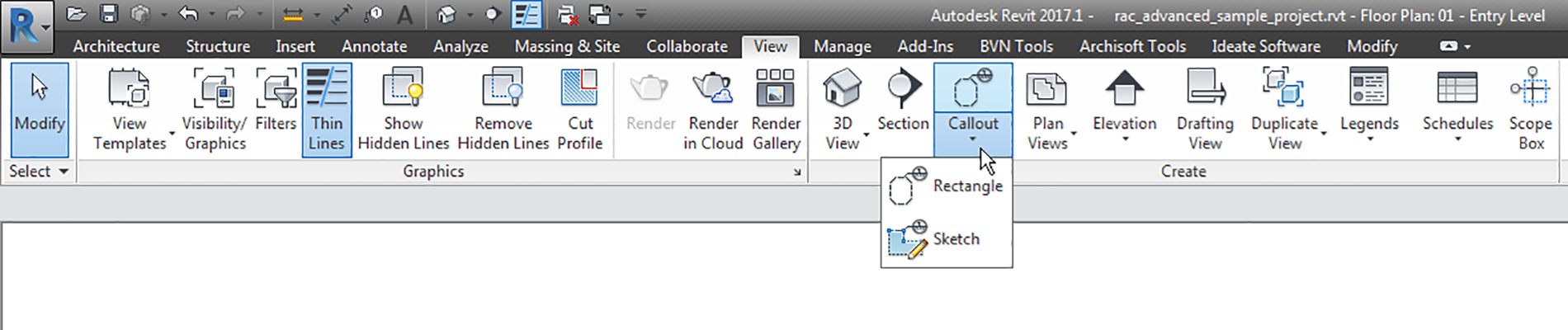

It is also possible to create a referenced callout. This type of callout can be used when you don’t want to reference the model directly, but rather to another detail, e.g. drafting views. To create a reference callout go View > Create > Callout and on the Options Bar, select ‘Reference other view’, and select a reference view name.

Drafting views
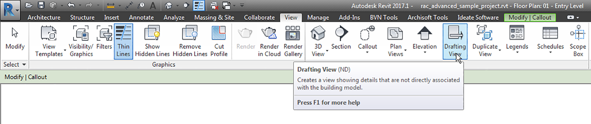
During a project, you may want to create details in a view that is not directly associated with the model. You can create this un-associated, view-specific detail using a drafting view. In a drafting view, you create details at differing view scales (coarse, medium, or fine) and use 2D detailing tools: detail lines, detail regions, detail components, insulation, reference planes, dimensions, symbols, and text. Drafting views do not display any model elements.
To create a Drafting View go View > Create > Drafting View.
Graphic representation – Lines
Before objects can be assigned a particular graphic representation, we first need to set the line graphics. This setting consists of three categories:
Line Weights
Model line weights control the line width for elements like walls and windows in orthographic views (plans, elevations, etc.). They depend on the view scale. There are 16 model line weights. Each can be given a size for each scale view. The sizes are loosely related to the nib sizes of technical pens used before the invention of CAD. A full set of pens would have the following nib sizes: 0.13, 0.18, 0.25, 0.35, 0.5, 0.7, 1.0, 1.5, and 2.0 mm, which correspond to the line widths as defined in ISO 128.
However, the International Organization for Standardization (ISO) called for four pen widths and set a colour code for each: 0.25 (white), 0.35 (yellow), 0.5 (brown), 0.7 (blue); these nibs produced lines that related to various text character heights and the ISO paper sizes. To modify the line weights go Manage > Additional Settings > Line Weights.

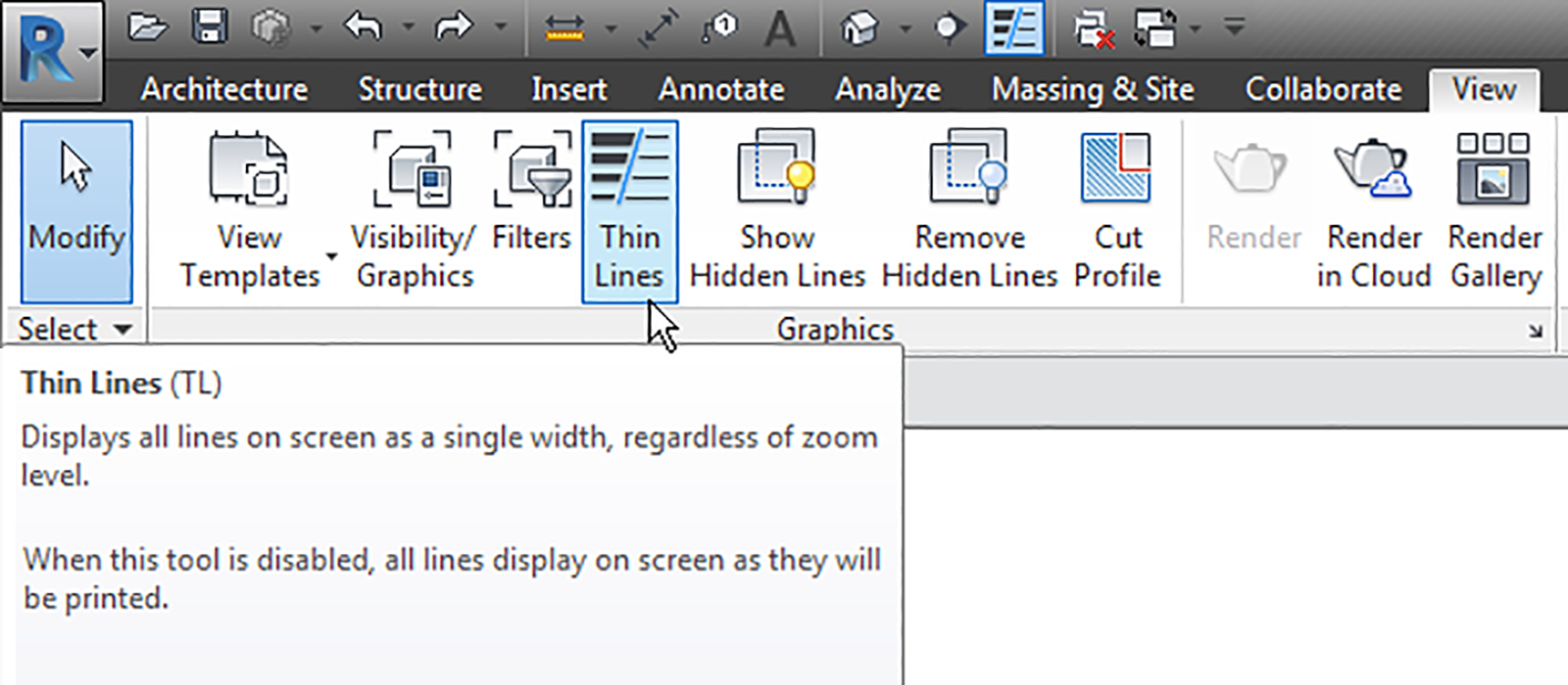
Note that to preview line weights in a view you need to disable Thin Lines (TL) by going View > Graphics > Thin Lines.
Line Patterns
Controls the line patterns such as dashed, centreline, etc. Regardless of if you have imported or linked AutoCAD drawings, then the default line pattern list will be contaminated. The best way to avoid this is to use a ‘CAD Links’ Revit model which is then linked into the main Revit model.
To modify the line weights go Manage > Additional Settings > Line Patterns.

Line Styles
Combines line weights and line patterns into a line style. To modify the line styles go Manage > Additional Settings > Line Style.


Graphic representation – Elements
Once the line styles have been established, we can then assign these styles to elements. This process can be done in several ways:
Globally
This will affect all objects in a particular category. To modify an object’s style globally, go Manage > Settings > Object Style.

By view
This will manually override the global settings by changing how all the objects in one category appear in that view. This approach can be combined with filters to identify specific elements, such as fire-rated walls. To manually override a view, go View > Graphics > Visibility/Graphics (VV or VG). Alternatively, select an object and right mouse click and choose Override graphics is View > By Category.

To add a filter to a view (optional):
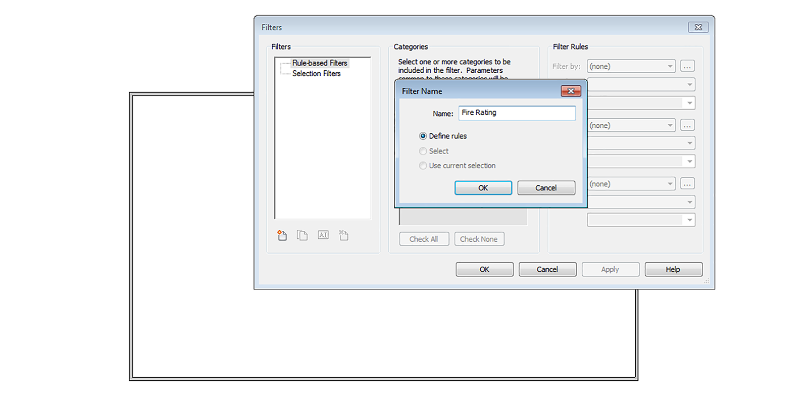
- Visibility/Graphics > Filters > Add > Edit/New. Or View > Graphics > Filters.
- Add filter and give it a name, e.g. ‘Fire Rating’. Use ‘Define rules’ as the option.
- Assign the relevant categories, e.g. Walls.
- Under Filter by, select a parameter, e.g. ‘Fire Rating’.
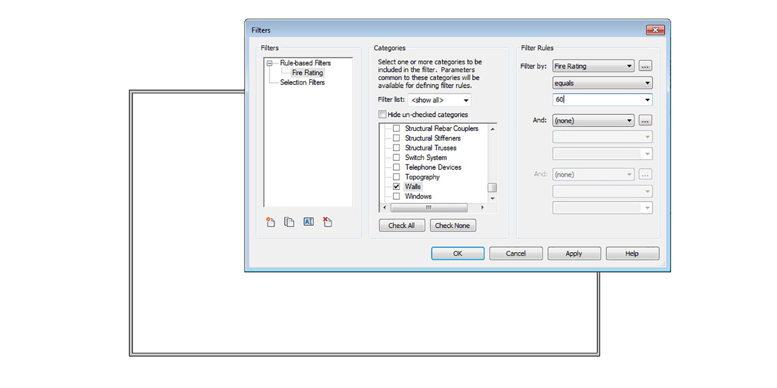
- Once the filter is created, assign it to the view by going Visibility Graphics (VG) > Filters tabs > Add and select the filter. Then set the overrides as required.

By element
This will modify only the selected element in that particular view. To override an element, select an element > right mouse click > Override graphics in View > By element.

Linework tool
Although the techniques above help you control the graphic representation of how elements appear, sometimes it doesn’t do what you need them to do. Lines might be heavier or thinner than you require. This limitation is where the Linework tool (LW) comes in handy; it allows you to modify existing lines in a view-specific context. To modify linework:
- Modify > View > Linework
- Choose the linestyle you want from the type selector
- Select the line or boundary of an element to change

You can also choose to remove lines using this tool. By selecting the <Invisible> line type, you can make some linework disappear. This tool is a good alternative to having to cover unwanted linework with a masking region (refer below).
Show hidden lines
Model and detail elements that are obscured by other elements can be displayed using the Show Hidden Lines tool. You can use the Show Hidden Lines tool on all elements that have the Hidden Lines subcategory. The Remove Hidden Lines tool is the inverse of the Show Hidden Lines tool. To show hidden lines, go View > Graphics > Show Hidden.
Regions
Regions are areas of any shape or size that you can fill with a pattern. There are two types of regions within Revit:

Masking regions
Masking regions are white boxes that can have (or not have) discernible borders to them. They are typically used to ‘hide’ or mask certain content from a view that you don’t want to be shown or printed. To create a masking region go Annotate > Detail > Region > Masking Region.
Filled regions
Filled regions allow you to choose from a variety of hatch patterns to fill the region. These are commonly used in details to show things like rigid insulation, concrete, plywood, and other material types. To create a filled region go Annotate > Detail > Region > Filled Region.

Beyond the ability to control opacity (transparent or opaque), two other variations of filled region types are available, Drafting regions (2D) and Model regions (3D):
- Drafting regions are a region type typically used for patterns. Some examples of a drafting region hatch might be diagonal lines in an area plan, or crosshatched lines to show the difference between two departments. Drafting regions are created by specifying a distance between two or more lines relative to the printed sheet.
- Model regions keep a consistent spacing relative to the model, not the view. You might use a model region to show ceiling tiles or brick courses, or tile pattern in a bathroom tile pattern. Model regions will keep their scale relative to the model.
Family library
Not all families need to be modelled from scratch. If the family you are after isn’t in the default Out-of-the-Box (OOTB)Revit library, try doing a quick search online. Here is a list of useful websites:
Components
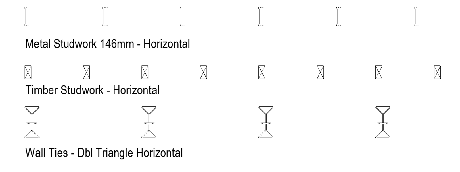
Detail Components are schedulable, taggable, keynotable 2D families that allow an additional level of standardisation within your model. Some examples of things you’d use detail components are blocking in section, steel shapes, metal studs in plan or section—just about any replicated 2D element that comes in a standardised shape.
You should use Detail Components wherever possible, rather than drafting lines. Detail components are more efficient, and they are easier to copy and constrain. Remember to lock or check the box ‘moves with nearby objects’ when placing them to ensure they move if the model does.
To create a Detail Component, go New > Family > Metric Detail Item. Draw as required and save. In the project go Insert > Load from library > Load family. Once loaded, the family can be placed in views by going Annotate > Detail > Component > Detail Component.
The Repeating Detail Components tool allows you to place a detail component in a linear configuration where the detail component repeats on a set interval. This tool allows you to draw a ‘line’ that then becomes your repeating component. An example of this would be brick courses.
To draw a Repeating Detail first create a detail component. Then load it into the project by going Insert > Load from library > Load family. Next, we need to create a repeating component from the detail component. Go Annotate > Detail > Component > Repeating Detail Component. In the Properties window, Edit Type and Duplicate. Change the referring detail to the one just created and modify the spacing. Draw a simple line to array the repeating detail component.

Insulation
The best way to think of the Insulation tool is like a pre-made repeating detail. Selecting this tool allows you to draw a line of batt insulation, much like a repeating detail. To draw insulation, go Annotate > Detail > Insulation. The width and the bulge ration can be modified in the Properties pallet.

Revisions
Revisions allow designers, builders and others involved in the project to track changes made to a set of drawings. This process is most important during the construction documentation phase. Since the construction documents usually consist of numerous sheets, this methodology allows everyone on the team to track and identify which changes were made and when they were made during construction. The purpose is not only to ensure correct construction but also to create as-built documentation recording how the building was created, to be delivered to building owners upon occupancy.
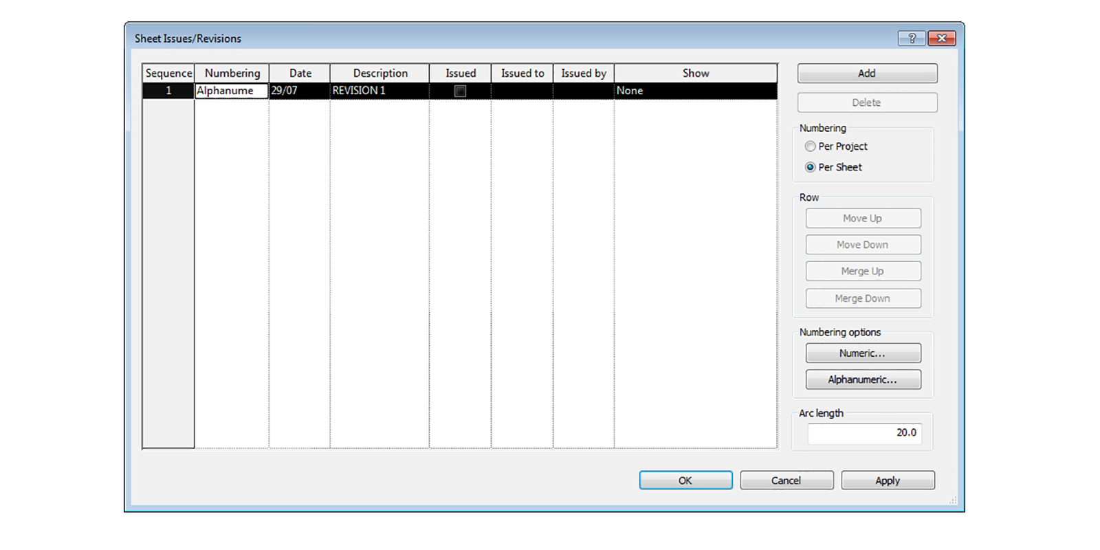
Creating revisions
To create a revision go View > Sheet composition > Revisions. Numbering is generally ‘Per Sheet’, and you can then choose between ‘Numeric’ (1,2,3, etc.) or ‘Alphanumeric’ (A, B, C, etc.).
Once the revisions are created, they then need to be applied to the relevant sheet(s). To do this, go to a sheet and in the Properties window, under ‘revisions on sheet’ apply the revision just created. This process will update the title block automatically.

Revision clouds
Revision clouds are used to identify the part of the sheet that has changed. To create a revision cloud, go Annotate > Detail > Revision Cloud. Note that for the clouds to be visible, ‘Cloud and Tag’ must be selected when creating the Revisions (View > Sheet Composition > Revisions).


8 Comments
yann
Well, if you link an autocad files, it wil also imports all the linepatterns.
paulwintour
Good pick up Yann. You are absolutely correct. I have updated the post. Thanks.
RAY FRISCH
This is what I was looking for. Great and very informative. Thank You for sharing it Paul
Yushi
A well organized and comprehensive article! Thanks
Tyler Doherty
^^^ Agreed! Thank you!
Dana Dahl
Well written article! Would like to know if people draw with details lines or filled regions. Seeing complete details drawn with filled regions make me want to jump off a bridge
paulwintour
Hi Dana.
Thanks for the feedback. I would recommend where possible you use detail components over detail lines. I wouldn’t recommend using filled regions for ALL the elements but then again. Seems a bit overkill to me.
Dana Dahl
Thanks for the Reply,
I do try and use as many detail components as possible. Since I do lots of renovation work, the standard out the box components many times do not work. Having learned my trade by hand drawing (pre-cad days), line work is extremely important to me. It is a sense of pride. A fine line exists between over drawing / spending too much time versus not having the information needed / monotone drawing. The designers get to show their talent by designing buildings. Drawing the details lets me show my talent. It is also my job to convey designers vision to the contractor.