
For a long time, splines in Revit have been a major bugbear. Splines can be created using either the Model lines (Architecture > Model > Model lines) or Detail lines (Annotate > Detail > Detail Lines) command. However, there are major limitations when it comes to editing splines. This tutorial discusses the limitation of splines and offers three possible workarounds.
Limitations
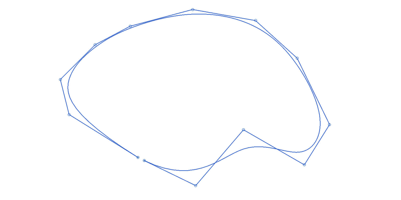
It is currently not possible to make a closed, periodic spline. Nor is it possible to trim the spline once created.
Furthermore, it is (still) not possible to snap to the start/end point so that the points are coincident. Note that if you try to move the start/end point directly, it will scale and modify the entire spline. To move only the start/end point, you need to use Tab to select it.
All of these limitations make working with splines very difficult. There is actually not much you can do with splines within Revit. However, here are your options if you do want to work with splines.
Option 1: Native Revit splines
Since you cannot create a single closed spline within Revit, you can either:
- Create a second spline or line and snap to the start and end point to fully close the spline. In this scenario, you’ll need to eye-in the tangency.

- Model an in-place mass which only has 2D linework in it. This method will allow you to snap to the end point, although technically it is not ‘closed’. Again you’ll need to eye-in the tangency. You will also receive an error stating that there are two overlapping points. This error can be ignored since if you try to delete the duplicate reference point, it will remove the last segment.
- Create an adaptive component family, which is similar to the in-place mass method described above.
Option 2: Imported AutoCAD/Rhino linework
The workaround for these limitations is to use AutoCAD or Rhino. Create or modify the spline in AutoCAD or Rhino, and then reimport the geometry back into Revit. When importing, you’ll need to use ‘Import CAD’, not ‘Link CAD’. Once in Revit, you can then explode the Imported CAD spline. Revit will convert it into a Revit spline and split it into two parts.
If a 3D spline is imported, it will be flattened to the current work plane once exploded within Revit. The method, of course, breaks the golden rule of not importing CAD geometry and especially not exploding CAD geometry. The CAD geometry, therefore, needs to be as ‘clean’ as possible and used sparingly.
Option 3: Dynamo
Using Dynamo to generate splines is probably the best workaround. Dynamo will allow you to create a closed, periodic NURBS curve, similar to what Rhino or AutoCAD can produce. The closed spline will need to be split into two segments to create Revit geometry, such as model lines or a floor. Although we are left with two lines, they will be tangential unless modified manually.
The final output of this workflow is similar to option two, where we imported CAD linework; however, the benefit Dynamo has over this method is that you won’t need to keep deleting and reimporting the geometry. Re-running the Dynamo script will automatically update the Revit elements should the spline geometry change.

Conclusion
Regardless of the workaround adopted, the functionality of splines within Revit is incredibly limited. For example, it is not possible to dimension to a spline nor to add a spot coordinate (except to the end points). Let’s hope that Autodesk finally acknowledges this limitation and build-in some additional functionality to solve this issue once and for all.


6 Comments
Chiquito de la Calzada
Very good article. What I’d love to do is to parameter the control points of the spline. My guess is that you can only do that if you work with a conceptual mass family, but it would be nice (or even something to expect from a 5k/year product) to be able to do so in a furniture family file
seychellian
Is it possible to add parameters to the spline. I am trying to make nice smooth scalable boulders and am struggling.
paulwintour
Yes you can add parameters to a spline. The best way is probably through an adaptive component though. However I tested this a few years ago and found that it crashed quite a lot. Not sure if that has improved. Of course the other way is simply to use Dynamo.
ROBERT HOLLANDER
I have been able to scale an object made of splines if I draw the object on a grid of reference lines. Then I change the scale between the reference lines and the object will follow… somewhat. It is far from exact. Beyond that, I don’t know of any way to constrain or add parameters to a spline (unless you are speaking about adaptive components rather than the standard family editor). I’d like to know.
ROBERT HOLLANDER
Not reference “lines.” I meant reference PLANES. Sorry.
Dash Bernhard
is there a more in-depth tutorial/video for using dynamo for this?