
This tutorial explains how to geo-reference your Revit model based on survey or Geographical Information System (GIS) data sets. Since geometry in Revit needs to be within 10 miles or 16 kilometres of the model’s internal origin, specific workarounds are required to maintain accuracy. By following the steps outlined below, it is possible to eliminate any graphical inaccuracies while maintaining the coordinate system. The tutorial uses Sydney as a case study. If you are unfamiliar with coordinates systems used within Australia, please refer to this tutorial.
Project Local Coordinate System
Many frequently used CAD/BIM software have inferior GIS capabilities. This can make geo-referencing models difficult. Revit, for example, has a maximum distance limit from its internal origin of 10 miles or 16 kilometres. Beyond this limit, the graphical representation of elements becomes less reliable and less accurate. This limitation applies to geometry created in Revit as well as incoming geometry from an import or a link.
Since surveys, city models and planning overlays are authored in GIS-enabled software, such as ArcGIS or QGIS, they are often geo-referenced and are located very away from the origin. Directly importing this information into Revit will cause an error, “Geometry in the file has extents greater than 20 miles (33km)”.

To avoid this issue, it is recommended to set up a ‘Project Local’ coordinate system. This is merely repositioning the model closer to the origin point and falsifying its coordinate values.
Step 1: Prepare the survey
Firstly, open the MGA56 positioned data set in AutoCAD and draw a circle at coordinate X=335,000m, y=6,250,000m (or some other known point if not in Sydney). Ensure all layers are turned on and unlocked. Select all elements and move the entire drawing from the centre of the circle to 0,0,0. The drawing will now be at the ‘Project Local’ coordinate system. The repositioned geometry will now be much closer to the Revit’s internal origin. This process should avoid any geometric error messages when linked into Revit.
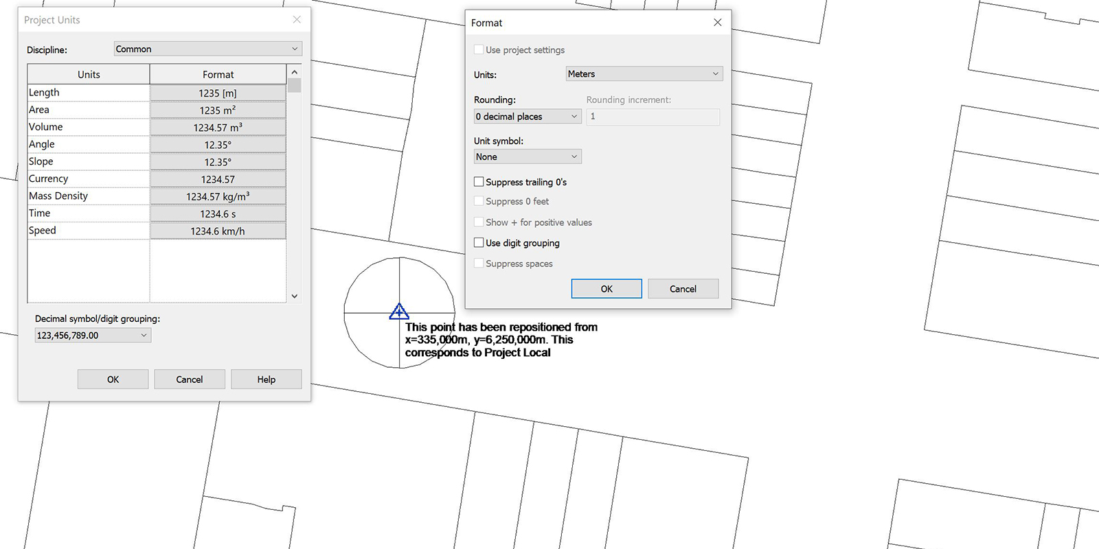
To make sure others are aware that the drawing has been repositioned, add some text at 0,0,0: “This point has been repositioned from x=335,000m, y=6,250,000m. This corresponds to Project Local.”

Next, as per best practice, clean up the CAD drawing by running Purge and Audit. To do a super purge, you can run ‘Wblock’. You may also want to explode blocks as sometimes the insertion point, which isn’t always visible, is far from the main geometry and can cause errors. Check that the insertion scale is set correctly to meters.
Step 2: Set-up Revit site model
In a new Revit model, ensure that the length units are set to metres. This is important as most surveys will be in metres while Revit models in Australia tend to be in millimetres. While it is possible to link files of different units, this may cause confusion in Step 3 and is best avoided.
Next, ensure you are in a view orientated to True North and then go Insert > Link > Link CAD. Select the repositioned project local file from Step 1 and use ‘Auto – Origin to Internal Origin’ as the positioning. Import units should be ‘meter’, and colours as ‘black and white’. Deselect ‘Orient to view’ and ‘Correct lines that are slightly off axis’.

The survey will be linked in at ‘Project Local’ coordinates and will be pinned by default.

Note that Revit only has two orientations – Project North and True North. Technically our survey data is orientated to MGA56 not True North, but for this example, we’ll consider them the same.
Step 3: Set Revit site model coordinates
The next step is to set the coordinates so that it displays MGA zone 56 coordinates without moving the Revit model or the linked *dwg file. To do this, first turn on the Survey Point by going Visibility Graphics > Site > Survey Point. It should be located at 0,0,0 if Steps 1 and 2 were done correctly.

Go Manage > Project Location > Coordinates > Select Coordinates at a Point, and select the Survey Point and enter in the MGA56 coordinates that this point relates to. It is important to note that in CAD programs such as AutoCAD, the convention is X,Y,Z. However, in Revit it’s N/S, E/W, Elevation so you’ll need to flip the order of the values accordingly.
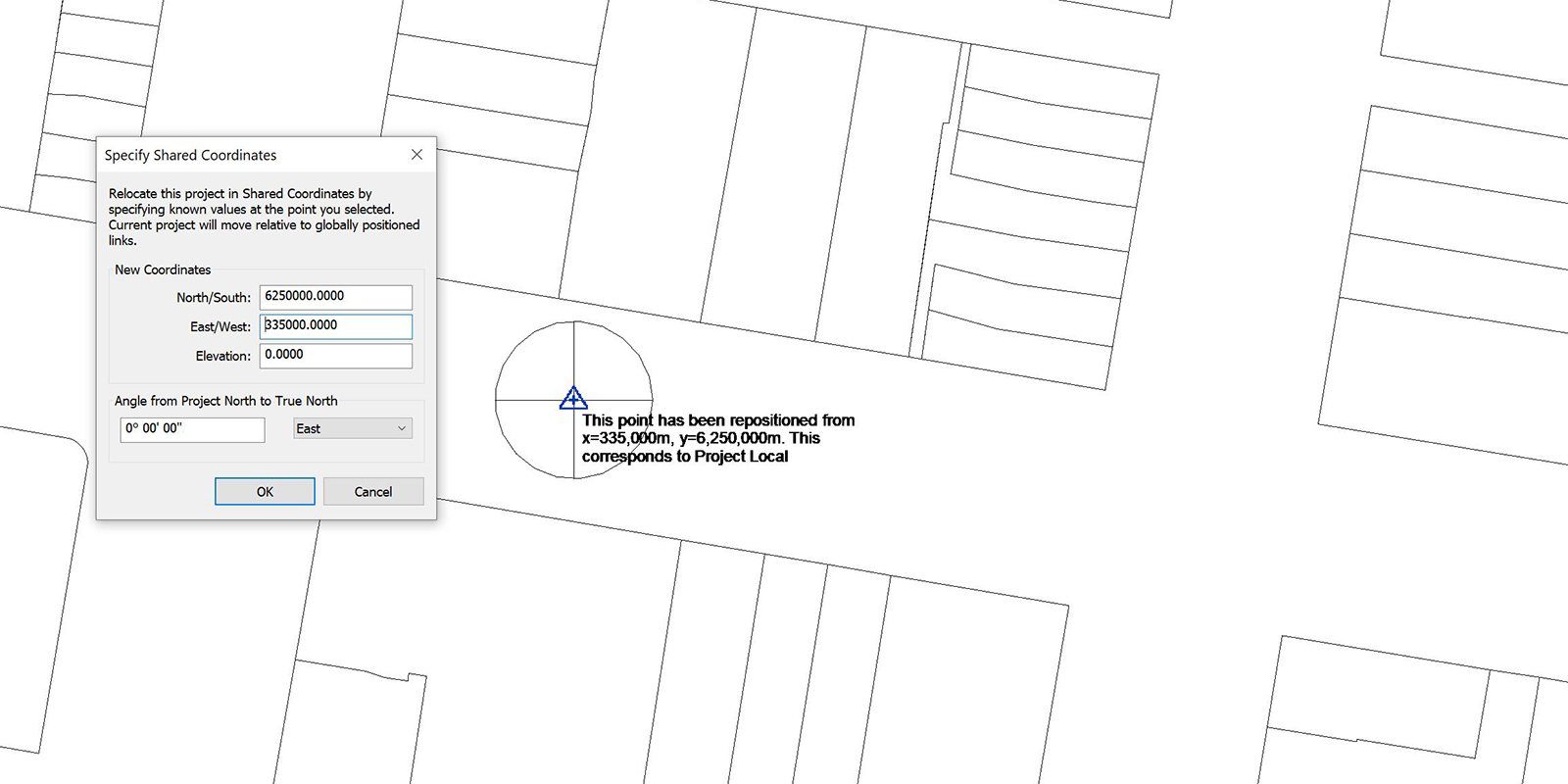
This will move the position of the Survey Point without moving anything else, including the Revit Project Base Point and Internal Origin which will be kept as-is. The Project Base Point will display the new coordinates, but it will still be coincident with the internal origin (0,0).

Step 4: Verify Revit coordinates
Without some visual reference, it can be challenging to understand a coordinate system. The simplest and easiest way to achieve this is to add a grid, typically at 500m intervals, with Spot Coordinates. By creating two Spot Coordinate types, ‘Northing_Horizontal’ and ‘Easting_Vertical’ you’ll easily be able to see if someone has accidentally moved the model. This is particularly important when using shared coordinates (refer Step 6).

Step 5: Set-up Revit’s building model (optional)
If you plan on linking in a Revit building model and sharing coordinates, first prepare the building model. Ensure the Project Base Point is coincident with the start-up location. To do this, select the project Base Point and unclip it (paper clip with slash). Next, right-click and select move to start up location.

You can model as much or as little information as you like, just ensure there are at least the two grids in there. Save and close the file. If the file isn’t closed, it may cause errors in the next step.
Step 6: Set-up shared coordinates (optional)
Next, we need to geo-reference our building relative to the site model. This can be done by either acquiring coordinates or pushing coordinates. This tutorial will describe the push method as I find it more intuitive.
Open the site model and link in the building model by going Insert > Link > Link Revit and insert the building model using ‘Manual – Origin’ as the position. Move and rotate your building as required so that it is in the desired position. Select the building model link and in the Properties pallet, click Shared Site and select the first option, “Publish the current shared coordinates…” and press Reconcile.
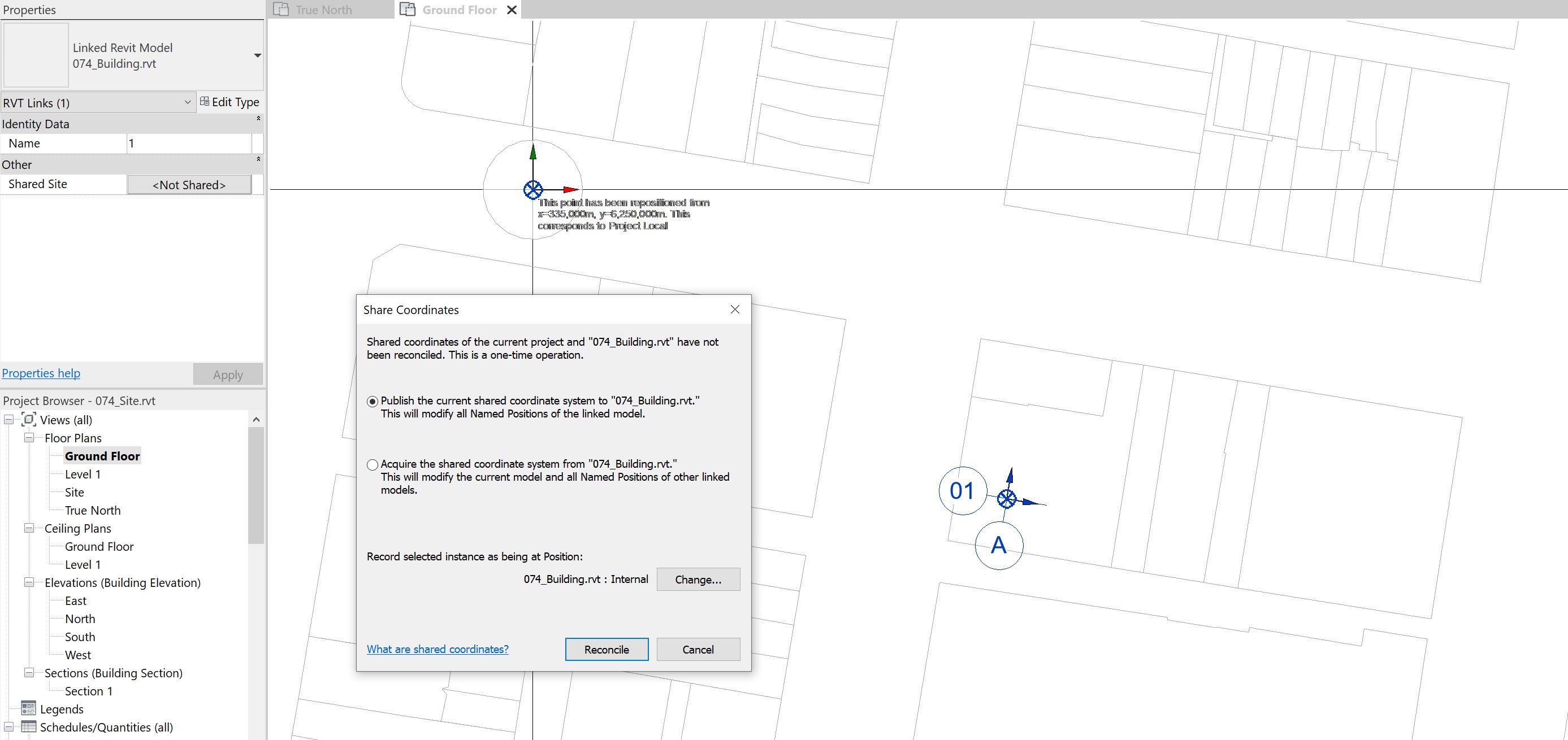
When you next save the file, you will be prompted if you want to save the position of this link. Select ‘Save’. You have now enabled shared coordinates.
Conclusion
Due to a lack of GIS capabilities, getting coordinates correct in Revit can be difficult. While it may be intuitive to keep all models and links geo-referenced for ease, this will invariably cause graphical representation issues which are less reliable and less accurate. By following the steps outlined above, it is possible to eliminate this issue while maintaining accurate coordinates.


18 Comments
Anthony Bowden
Hello Paul,
For pushing coordinates to the linked model you suggest “Select the building model link and in the Properties pallet, click Shared Site and select the first option, “Publish the current shared coordinates…” and press Reconcile.” I’ve always used Manage > Project Location > Coordinates > Publish Coordinates. The two methods appear to do the same thing. Is there an advantage you see in the former?
Thanks,
Anthony
Michael Dunn
And in our new social distancing BIM 360 Design world I’ve read that we can’t use publish coordinates at all so we need to use the acquire coordinates method.
paulwintour
Yes that is correct. BIM 360 is a low trust environment so you can only acquire, not publish.
Anthony Bowden
We’ve got to fully detach here.
paulwintour
Hi Anthony. Yes both do the same thing although you’re method would probably be better for multiple linked models.
Invzibl
Anthony, you are correct. There is no difference between the two methods.
Anthony Bowden
Curious then why they seem to use different terminologies on the two different commands.
paulwintour
Autodesk aren’t always consistent with their terminology. Plus it might be different on BIM360
Greg McDowell Jr
Why do people insist on having something at the Revit Internal Origin?
I mean sure, if you really want it, but what happens if the grids move? Do you relocate the rest of the building around the intersection? And what if you don’t know where the grids are when you start the model? Unless you’re waiting until you have designed a fair amount before getting into Revit?
Different strokes perhaps.
paulwintour
It’s not essential but it does make things easier. Firstly it helps with maximum distance limits. And secondly it helps with interoperability. In the past when working with plug-ins like hummingbird or gevit, the internal origin was used by default. Have to translate geometry after imported was just a pain. With Revit 2020 showing the internal origin and more flexibility with plug-ins maybe it’s less important now days.
paulwintour
This post talks a bit about these issues: https://parametricmonkey.com/2016/12/22/revit-coordinate-systems/
Anthony Bowden
Paul, what is your method for getting correct shadows out of this file noting that it is oriented to MGA not the real True North?
paulwintour
Yep that’s a tricky one but I’m putting together a tutorial on it so stay tuned!
Anthony Bowden
This one has bothered me for a long time. I can set up an additional named Site within a single file project, but where there are multiple files and shared coordinates involved it gets challenging. For those one’s I’ve found the need to set all the links in the project master (site/podium) file to be Attachment, then link that into a new empty file, and then rotate it to the real True North. Then I run my shadow studies out of that file. If you have something better I’d love to hear it. Good luck.
Anthony
Chris Rossetto
I’ve witness many heated disputes between BIM Managers about this. Great article, thanks for the thorough explanation and comforting to see as we employ more or less this as the preferred method on all of our projects. There are heaps of great benefits to running a site file:
1. The ability to relocate the building’s position in relation to the site/boundary without moving actual geometry.
2. Setting up clean ‘Linked Views’ of isolated information such as set-outs, survey boundaries, rail aliments or annotated graphical site plans that can be consistently displayed (By Linked View) into multiple building model plan views at any level as background info. Saves you a heap of graphical overriding, duplicating 2D elements and playing with view ranges in your building model.
3. You can maintain a local origin-origin coordinate system on the XYZ axis in your building model which is much easier for interop with Rhino, Grasshopper, Dynamo and other plugins as you’ve mentioned.
paulwintour
Heated disputes between BIM Managers? Never! Glad you found it useful.
Stuart
What do you do when the Revit Model is already placed in it’s Geo Location (about 1100miles [2500+ km])??
Currently, I am experiencing issues with graphic inaccuracies in a linked CAD site plan.
– when I export the revit to CAD; Linked CAD is graphically distorted.
I thought about moving the Central Model to 0,0,0 – However Revit says it cannot move the model so far from it’s project start up location.
Please help!!
paulwintour
Hi Stuart.
It’s a little challenging to say without looking at the model. The issue is less about the model being georeferenced or not, but where it is in relation to the Project Start-Up Location. Are the inaccuracies in the CAD link or the Revit model? Are you able to post a link to a screenshot?