

Building Information Modelling (BIM) has brought about significant improvement to the Architecture, Engineering and Construction (AEC) industry. As this article will explore, however, is that the enforcement of specific BIM deliverables can be counterproductive and result in worse project outcomes. Specifically, the article unpacks the requirement of a fabrication-level model, known as ‘LOD400’.
When challenging the fitness-for-purpose of BIM, some readers may be inclined to jump to the conclusion that if you are challenging BIM, you must be advocating CAD. This assumption is misguided. For those that know the work of Parametric Monkey, they will recognise that our positioning is based on a deep understating on BIM’s strength and weaknesses and current industry trends. This article is therefore not about reverting to CAD, but rather questioning how together, we can improve the BIM process to achieve better things.
Level of Development
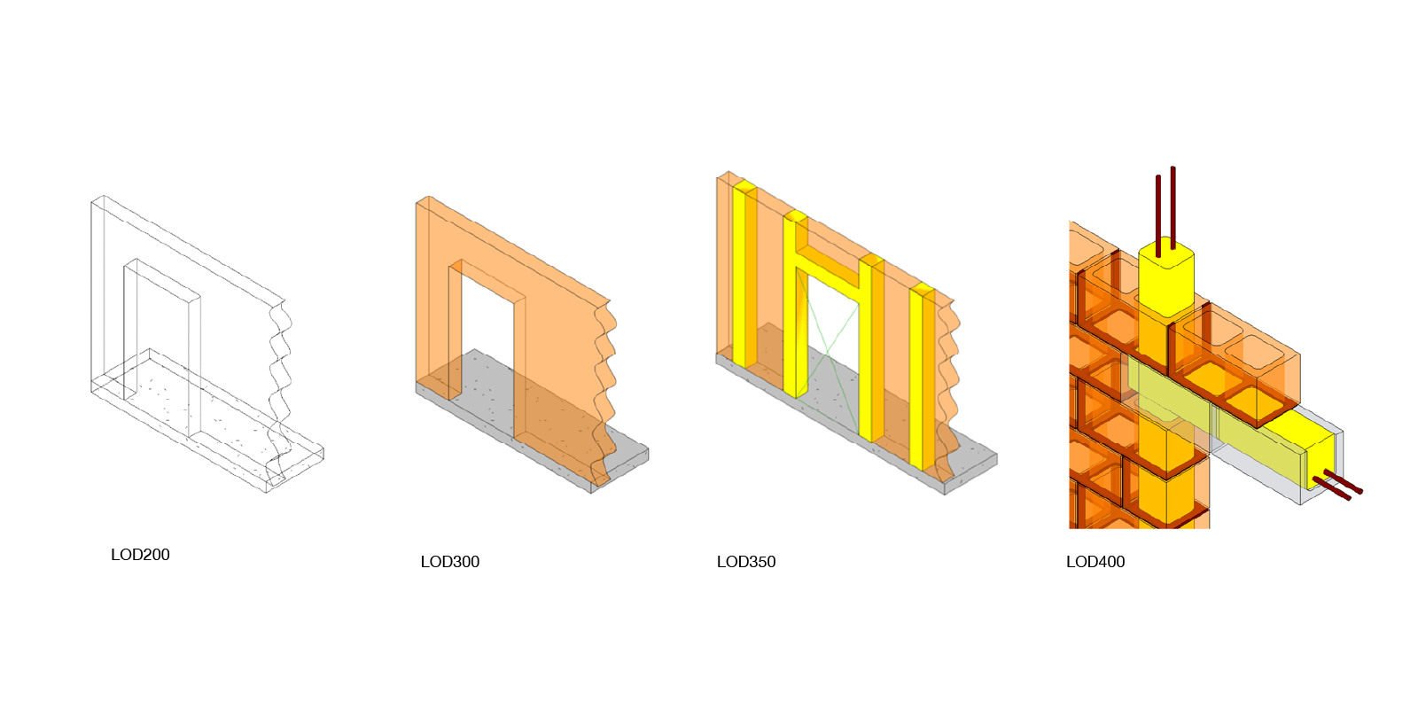
Central to the BIM process is the philosophy of gradual model refinement. This philosophy is best illustrated in the Level of Development (LOD) specifications found in guides such as the BIM Forum1. This much-cited guide shows how an element is progressively refined from a generic representation (LOD100) through to an accurate, as-built model (LOD500). The guide makes explicit that “it does not prescribe what Levels of Development are to be reached at what point in a project but leaves the specification of the model progression to the user.”2 The guide is, therefore, a reference to articulate the content and reliability of a model. While the LOD definition makes allowances for non-graphical information, this article is specifically focused on the graphical content of the elements.
The problem
It is often assumed that the more resolved a BIM model is, the better the outcome. This assumption, in turn, leads to the client or contractor-side BIM manager to specify that certain elements be modelled to LOD400. LOD is defined by the BIMforum as follows:
An LOD 400 element is modeled at sufficient detail and accuracy for fabrication of the represented component. The quantity, size, shape, location, and orientation of the element as designed can be measured directly from the model without referring to non-modeled information such as notes or dimension call-outs.
BIMForum4
You might be asking, how does developing a BIM model to a high level of development possibly result in a worse project outcome? Well, here’s why. Below, we illustrate two scenarios. The first is what many imagine BIM to be – We’ve called this ‘BIMtopia’. The second scenario is what we’ve witnessed time and time again on projects that we’ve been involved with across multiple countries. As you will see, there are several unintended consequences from what was intended. We’ve concluded that this dynamic is not an isolated one-off but rather a systemic issue in the AEC industry.
Scenario 1: BIMtopia
In scenario one, we follow the textbook BIM workflow, which looks something like this.

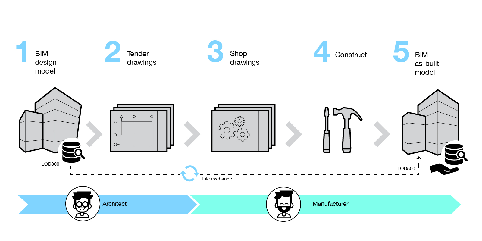
Stage 1: LOD300
A design model is authored by the architect usually to LOD300, where LOD300 is defined as model elements being “graphically represented within the model as a specific system, object or assembly in terms of quantity, size, shape, location, and orientation.” In other words, they are a reasonably accurate approximation of what should be constructed for coordination purposes. In the case of a LOD300 exterior window wall, for example, we know its location, overall dimension and spacing of mullions. But the element does not contain sufficient detail to accurately describe how it should be manufactured or assembled as neither the mullion profile nor the actual dimension of the glazed pane is defined.

Stage 2: Tender drawings (optional)
From the LOD300 model, the architect extracts 2D views and produces a set of tender drawings. Note that this step is indicated as optional and in an ideal BIM process, many would argue that this step should be skipped, with the BIM model forming the tender information.
Stage 3: LOD400
Once the contract has been awarded, the various sub-contractors take ownership of the BIM model and continue to develop the model to LOD400 as per the BIM Execution Plan (BEP). That is, the BIM model becomes an accurate representation of what is to be fabricated, including reinforcement, fixings, sealants, flashings and membranes.
Stage 4: Shop drawings
Most BEP contain clauses to the effect that all 2D views must be extracted from the BIM model. Therefore, all 2D shop drawings are dynamically linked to the BIM model to minimise potential coordination issues.
Stage 5: Construction
Unless there were any on-site changes, little to no modification is needed to update the BIM model for as-built (LOD500) submission.
Scenario 2: BIM as an afterthought
In scenario two, market forces dictate changes to the preferred BIM workflow, as outlined in scenario one. We call this scenario “BIM as an afterthought’.
Stage 1: LOD300
As per scenario one, a design model is authored by the architect, usually to LOD300.
Stage 2: Tender drawings
As per scenario one, the architect extracts 2D views from the LOD300 model and produces a set of tender drawings.
Stage 3: Shop drawings
Once the contract has been awarded, the various subcontractors take ownership of the BIM model for their package. But instead of developing the LOD300 model as in scenario one, the subcontractors take the architect’s 2D tender drawings and develops them to produce their shop drawings. This process breaks the golden rule of gradual model refinement.
Step 4: Construction
Once the shop drawings have been signed-off, and elements are in production, the updating of the BIM model to LOD400 is out-sourced to a third-party.
Step 5: BIM as-built
The BIM model is submitted at the end of the project to fulfil a contractual deliverable.
Cause and effect
Why does this occur, and what are the so-called market forces driving this change? We’ve spoken to many subcontractors and manufacturers, and the overwhelming response is unsurprisingly time and money. They tend to occur at three main points in time:
Tender
As projects progress, it is common for concessions to be made on the contractual BIM deliverables. Knowing that this will likely occur, many subcontractors are reluctant to submit a tender price that includes the full BIM deliverables for fear that they will be priced out of a job. The main contractor accepts the lower tender because they too don’t wish to be priced out of the bid. Win the job first, then deal with the deliverables.
Contract award
Most construction projects follow a waterfall model whereby project activities are broken down into linear sequential phases. A critical path can be established, stating when each package or system must be approved to achieve the desired end date. The subcontractor puts forward an argument to the main contractor that specific BIM deliverables need to be relaxed to meet the critical milestones. The contractor agrees with the caveat that the BIM model must be submitted at the end of the project. The priority is to complete the building on time – the digital model is supplementary.
Design development
Progressively developing a LOD400 model in parallel with design development is a slow process. Not because the modelling process is necessarily slow, but because of the stop-start nature of the approval process. Like most things, it is often quicker and easier to complete something in one go once everything is resolved. Since subcontractors and manufactures tend to use either AutoCAD or manufacturing-specific software such as Inventor or Solidworks, many prefer to use the software they are comfortable with and resolve any BIM deliverables at the end. Moreover, by adopting this approach, the BIM deliverables may have been relaxed to such an extent that far less effort is required.
Deliberations
At this point, one might point out that the value BIM offers is far higher than its cost. As a general principle, I agree with this statement, but when it comes to LOD400 models, I’m not so sure. Of course, there are many elements which should be resolved to a LOD400 level. But there are also many which do not. I see two main related factors influencing if a LOD400 model should be adopted, and when it should not.
Shop drawings vs fabrication drawings
There is a common misconception that shop drawings are the actual drawings that an element will be fabricated from. While this might be true for some items, often there is an additional set of drawings produced for fabrication. Shop drawings are therefore used for the approval process, whereas fabrication drawings are used for the actual fabrication process.
This distinction is evident in our article ‘UTS Central: A case study in digital fabrication‘. In this project, there were remarkably few shop drawings produced. Those that were produced showed typical connections and non-graphical information. The rest of the graphical information was shown in the model. The architect then used this model for the approval process.

Another set of drawings was then created with the unfolded pattern of each element. These fabrication drawings were then nested and fed straight into the CNC machine. This set of documents didn’t form part of the approval process. Their purpose was solely to improve the fabrication process. By automating the process of generating 2D fabrication drawings from the 3D ‘shop drawing’ model, there were enormous benefits. The least of which was the fact that the LOD400 model served a purpose beyond a mere BIM deliverable.
Level of information needed
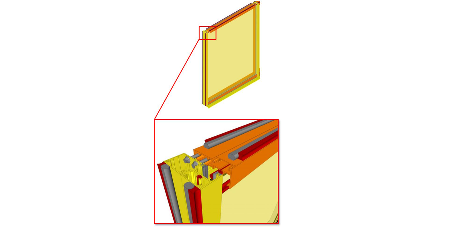
However, consider the example of the exterior window wall highlighted at the beginning of the article. Once a glazing system is chosen, is it really necessary to model every fixing, backing rod and sealant in 3D? What purpose does this serve?
A manufacturer doesn’t need this information. They have already manufactured their product thousands of time before and know how it goes together. The architect doesn’t need this information. They just care what the system looks like and that it works. The client doesn’t need this information either. They just need to know what system it is, who supplied it, and the associated warranty information.
Even clash detection is a moot point. After superstructure, the façade is the next element in the building hierarchy. If something clashes with the façade, it’s the other element that needs to move, not the façade. And in any case, detailed 3D models of concealed fixings and silicon joints are unlikely to impact any clash detection results. In this example, I would argue that a LOD400 model is not providing any additional benefit. Especially if it is provided at the end of the project.
Recommendations
So back to our two scenarios – instead of asking for a LOD400 model from the subcontractor, it would have been far better for the main contractor to ask for a LOD300/350 model. Why? Because updating the architect’s existing LOD300 model to an accurate LOD300/350 model is much more achievable. It is therefore much more likely to happen. The main contractor and subcontractor could have then benefited from progressive model development and performed all of the tasks one expects – clash detection, 4D and 5D scheduling, etc. But by enforcing a LOD400 model, they received additional detail but which was of little benefit to anyone. By asking for less, they would have received more.
Conclusion
This article shows that while it is possible to arrive at the same end-state, the two processes are very different. To get the best project outcomes, we recommend that LOD400 requirements be reserved for specific elements where the digital model will be used for fabrication, such as steel structures, ductwork, CLT, etc. This mindset requires restraint from BIM managers when writing BIM execution plans, to avoid making blanket LOD assignments and instead adopt a more nuanced approach.
References
1 The Associated General Contractors of America Inc. (April 2019). Level of Development (LOD) specification part 1 & commentary: For Building Information Models and Data.
2 The Associated General Contractors of America Inc. (April 2019). Level of Development (LOD) specification part 1 & commentary: For Building Information Models and Data, p.4.
3 The Associated General Contractors of America Inc. (April 2019). Level of Development (LOD) specification part 1 & commentary: For Building Information Models and Data.
4 The Associated General Contractors of America Inc. (April 2019). Level of Development (LOD) specification part 1 & commentary: For Building Information Models and Data, p.13.
5 The Associated General Contractors of America Inc. (April 2019). Level of Development (LOD) specification part 1 & commentary: For Building Information Models and Data, p.80.
6 The Associated General Contractors of America Inc. (April 2019). Level of Development (LOD) specification part 1 & commentary: For Building Information Models and Data, p.82.


19 Comments
Cameron
Great write up Paul. We are still dealing with the ‘sales pitch’ ideals of “BIMtopia”. In practice it is harder to achieve
paulwintour
Thanks Cameron. Glad you enjoyed it. Yes, the vision and reality don’t always align, unfortunately.
Damien
Top article Paul – we live in a world of over specification due to folk often not being grounded in reality. Great piece
paulwintour
Hey Damien, good to hear from you! Yes I think there is a lot of butt covering happening when BIM managers write BEPs. But having said that, sometimes these are written before the design or manufacturing process is know, which makes things hard.
Tony
Great thoughts Paul. Theory (e.g. LOD rating) should be reviewed based on results of (good) practice. Thanks for sharing it.
paulwintour
Thanks Tony. FJMT is certainly one of the leaders when it comes to engaging with the file-to-factory process.
Pierre Venter
We need to use checklists, we need to understand the bigger picture of design to completion and the steps in-between. Not all projects are in this realm. Contractual influences like Design/Build and no Project Team sharing philosophy ensures that there are gaps. I like the submission, well presented.
Pieter Rautenbach
Great article Paul, very true that more detail is not always better.
paulwintour
Thanks Pieter. Glad you enjoyed it.
rspeicher2013
Excellent discussion of the issues!
Teo
Nice one. And yes I agree with the other comments that it is refreshing to see a down-to-earth approach among the flood of “philosophical” BIM requirements being circulated online these days. One note though: I believe it makes more sense to refer to LOD at an element level rather than at a whole model level. In such a case you could still end up having certain elements modeled at LOD 400 in a model where the majority of the elements are at LOD 300/350.
Izabella
I strongly agree with your note, @Teo. Advanced bim guys understand what Paul was talking about and simplification behind that. But still there are plenty of not so educated ones, who will read it. I think that it may be highly confusing for them and worse, they usually overuse this statements like: “LOD300 model”, “LOD400 model” when they really think about LOD of element.
Paul Wintour
Just to clarify – the post describes elements modelled to a LOD. Not the entire building. The confusion may arise by the use of ’LOD model’. But a model is always an aggregation of elements – you don’t submit individual models per elements. Models are broken down by trade/sub contractors. And typically the granuality of LOD defined is consistent through trade packages. For example the entire facade to LOD400 as opposed to mulions at LOD400 and transome LOD300. But I take you point.
george stevenson
Excellent article Paul – and covering a point I have made many times that CNC machines require different information in different formats that are naturally added to AEC 3D BIM Model. A classic example of that is CadDuct where AutoDesk has invested a lot of effort trying to take the functionality and replace Autocad with Revit. In my view, it is a very niche area and, if CadDuct (or Autodesk Fabrication does the job, why not build on that?
However, this comes back to the wider question of is BIM and information model or a 3D model. Like most people, I would argue both but much of the information we need is never modeled in 3D – and nor should it be. As an asset manager, I would want the detail of the door closer and fire stopping of a door to be delivered as computer-readable data but I don’t need them modeled.
The “Information” should only be added to parameters in the 3D model if there is value in doing so – otherwise it should be managed in databases which are interlinked to the spatial model – the federation of which I would argue is the Full BIM Model – not simply what is needed for Coordination and Clash Detection
This is why the official IFC MVD for handover isn’t 2×3 (Coordination View) but COBie – which doesn’t require the 3D model.
Following on from that, we have a team of cross-industry people doing work on the management of change between the M&E design model and the M&E contractors model and how we can retain what is now referenced as the Golden Thread.
I would be interested in engaging with anyone else who finds this topic of interest and is willing to contribute to, and learn from, our collaboration.
Kris Weeks
Paul, really interesting read. A couple of thoughts: Design principals (not as familiar with LOD requirements) and BIM Managers (not as likely to have construction site experience) who issue the BEPs as part of the design contracts don’t realize the negative impacts of what you note in this article. A simple fix may be to have a technical architect sit with the BIM Manager when authoring the BEP. They could hash out where more detail would be beneficial versus harmful.
My other thought is that BEPs always stop at construction. They don’t take into account what the owner needs. Owners would often benefit from LOD 500 information for select equipment, but I don’t think it needs to be a linear path through LOD 400. I like your idea of LOD 300/350 for design & construction, skip LOD 400 or allow subcontractors to develop LOD 400 from the original BIM models if it helps their delivery, and require the subs to model LOD 500 on select items for the owner’s benefit (like exact make & model of large HVAC equipment, serial number, date installed, maintenance info, etc.) This can be used in CMMS and other facility management software.
Shane Ridley
Good article, Paul. Insightful, pragmatic, sensible. Less is more it seems applies to BIM, too!
Nguyên Nguyễn Thị Thanh
Thank you so much for your article! We usually use a checklist to clarify LOD requirement before getting started with the process of modeling.
Dave
Hi Paul, good honest assessment. Question though, the plant and process industry doesn’t maybe work this way – but focuses on the ‘digital asset’ as a handover. Piping, supports, racks, steel, concrete etc. Software then has been designed and coded to support that market need. Those parts pass through LOD’s of sorts – not by changing geometry but by being signed off the next LOD.
I asked BIMforum guys on a call a few years back why they persist in showing LOD is about changing geometry – the answer was ‘because our software can’t handle detail’.
So maybe that’s the answer – if Revit could actually handle massive amounts of detail – like Industrial software is kinda better at, then we wouldn’t be having this conversation? You simply just work up the model, maybe even using massive amounts of detail in early stages to establish exact clearance but that gets simplified in GA drawings etc. We don’t do that, since the software simply dies right?
Maybe this is software of the future but good to realize maybe that LOD’s kinda failed to bring massive benefits to the project value chain because the AEC designer software houses were too busy on-boarding the 2d generation and making sure they can those GA drawings issued as easy they could with Autocad?
Paul Wintour
Hi Dave.
The software limitation of being able to handle the level of detail is problematic. But the main reason for LOD, is the abilty to agree on the definition of done. And I think this is where it becomes problemtatic. As others have said, more detail doesn’t means it’s more accurate.