
270 Park Avenue serves as the global headquarters of JPMorgan Chase. Parametrically derived from a set of rules, the external plaza exemplifies innovative parametric modelling and digital fabrication, resulting in a distinct, crafted softness. Each of the over 14,000 individual parts was crafted from Giallo ornamental granite in Carrara, Italy, before being transported to New York for installation.
Introduction
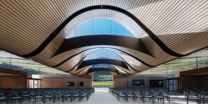
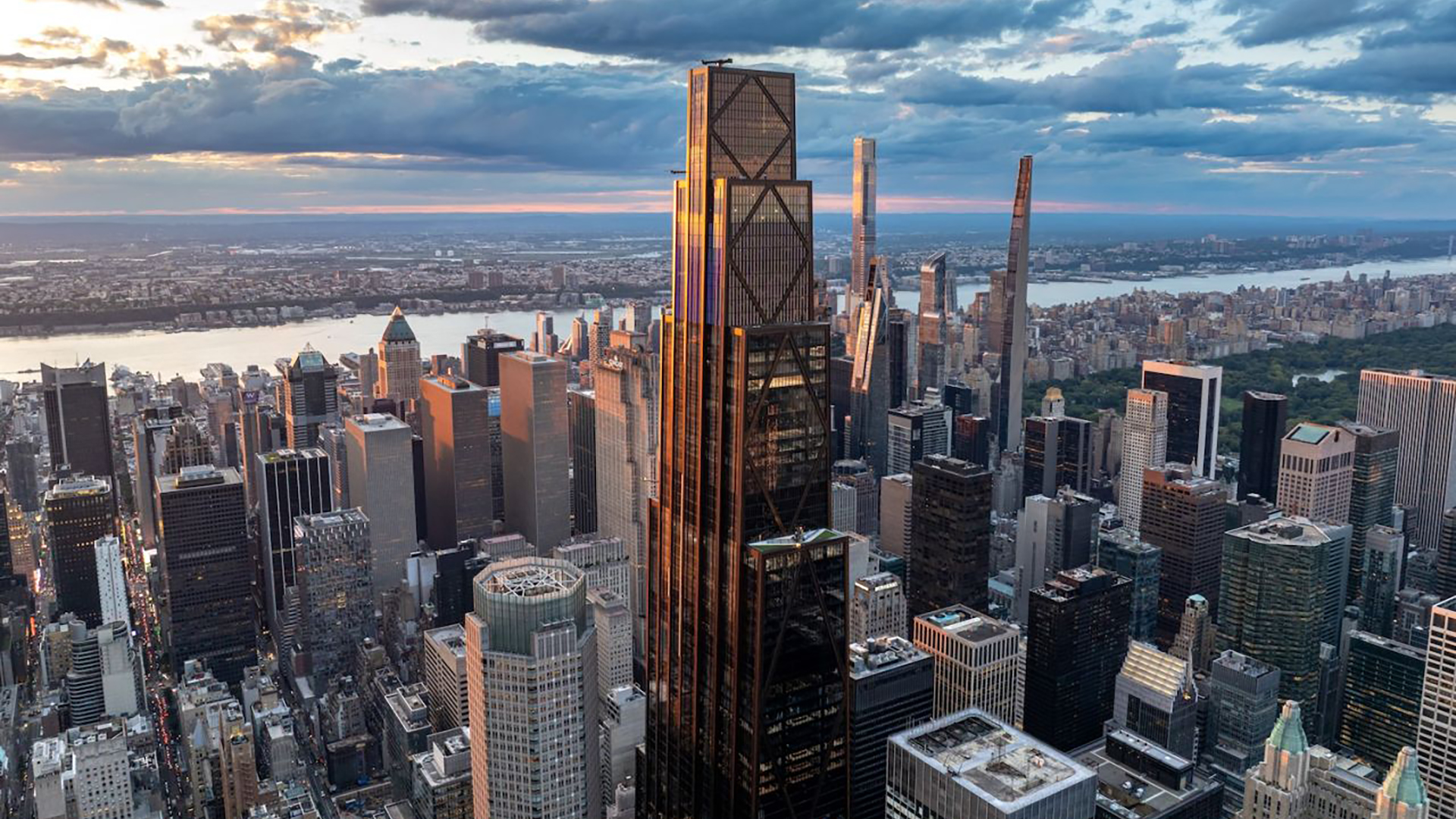
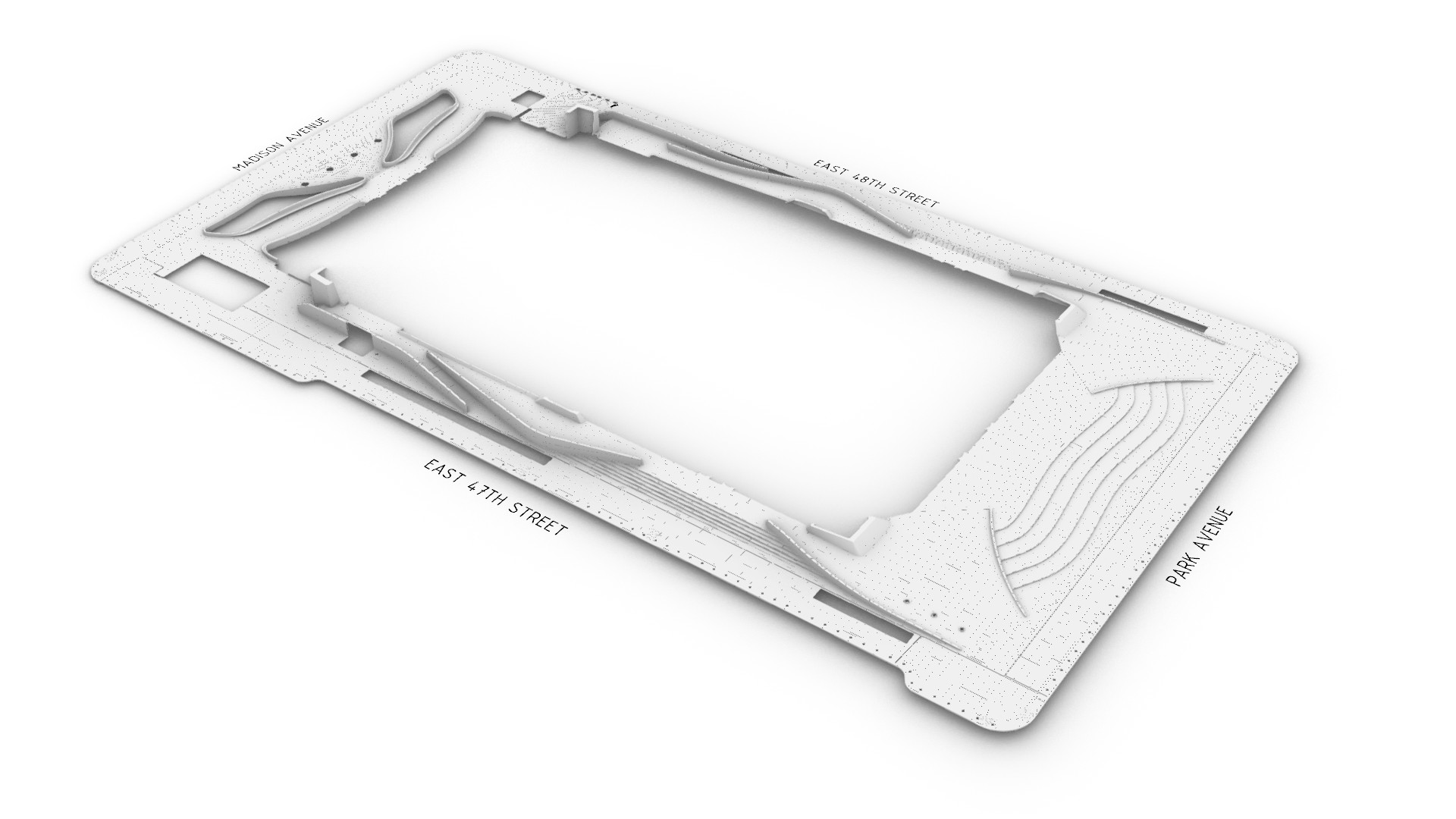
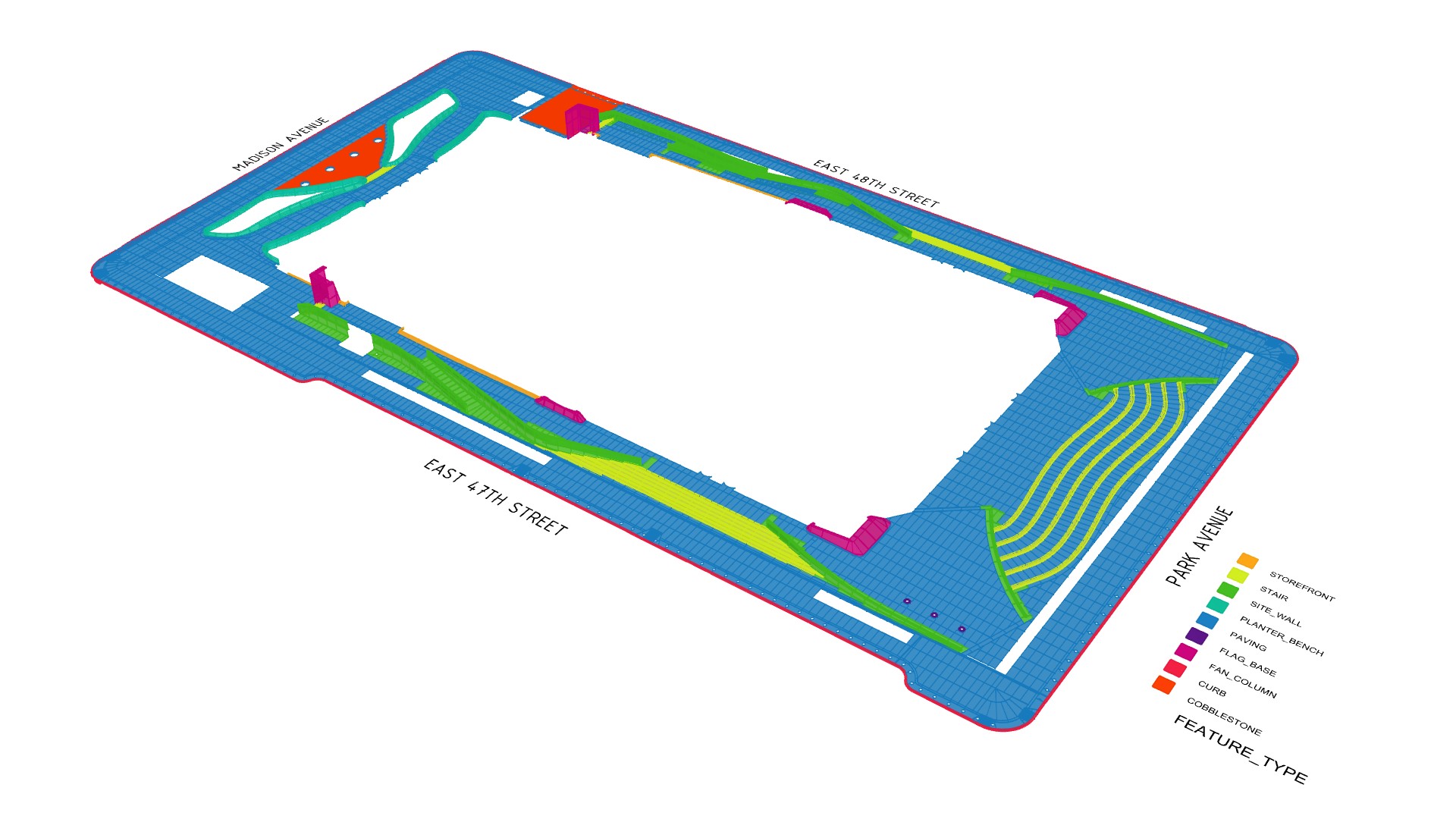
270 Park Avenue is a 60-story skyscraper in New York City, designed by UK architecture studio Foster + Partners. Located above Grand Central Terminal, it occupies an entire city block in downtown Manhattan, bounded by Park Avenue, East 47th Street, Madison Avenue, and East 48th Street. At 423m, it is the sixth-tallest skyscraper in New York City and serves as the global headquarters of JPMorganChase. The project officially opened on 21 October 2025 with an estimated cost of US$3 billion.
Scope
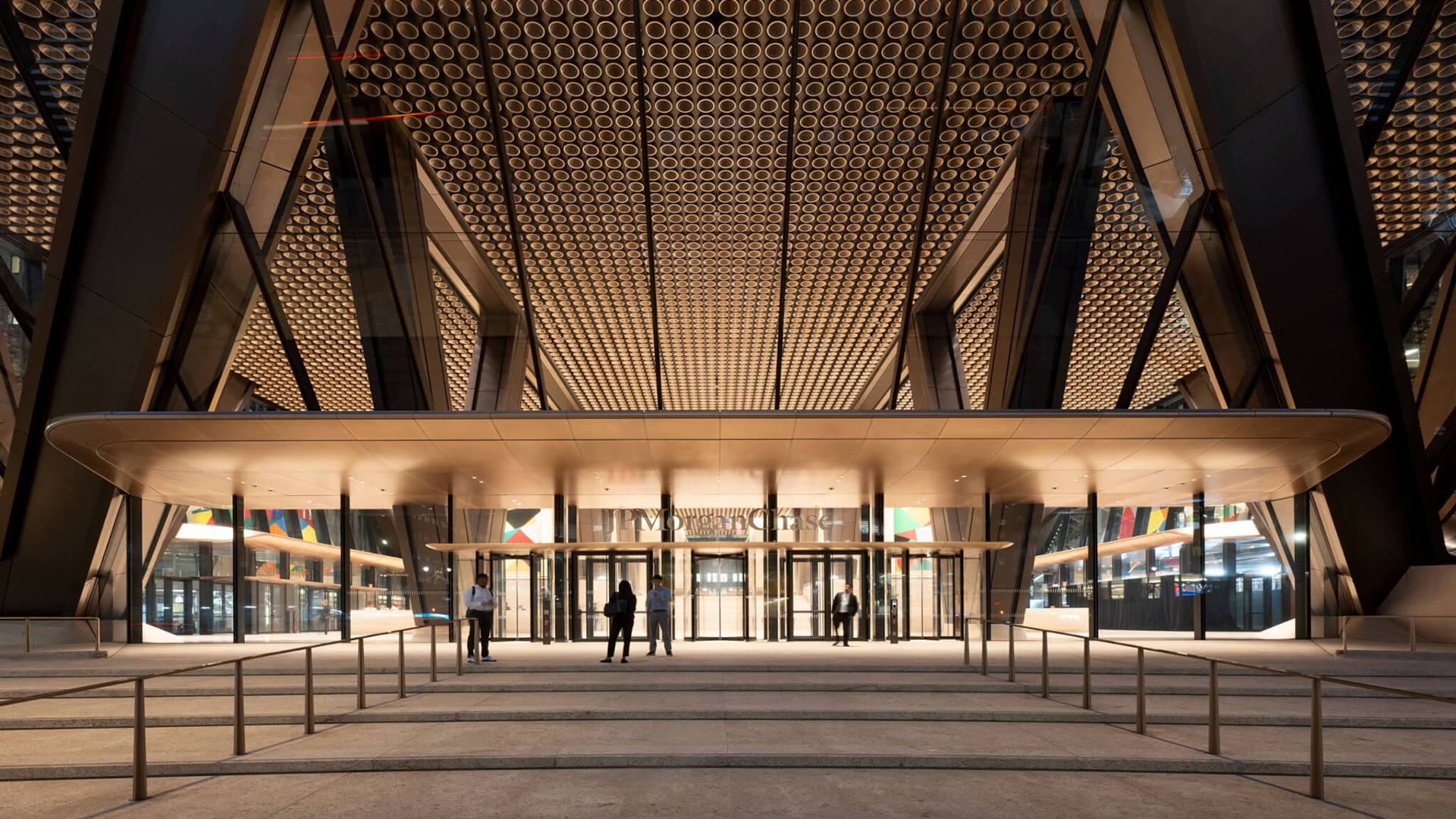
At its base, the new building is supported by a unique truss system that allows its structure to touch the ground in only a few places. By cantilevering the structure, the design creates 4,800 square meters of public plaza, 2.5 times the previous building. The external plaza consists of four zones and spans approximately 130 x 70 meters. Its design is centred around crafted softness, welcoming users as they move from the curb through to the lobby.
Project team
Given the complex nature of the plaza design and the need to ensure geometric precision, a dedicated digital team was assembled to provide parametric modelling and design-to-fabrication services. Neil Thelen of Thelen Design Group initially led the team, with Chris Galbraith of Galbraith Design Studio taking over partway through the project. Parametric Monkey was commissioned to generate the design model and develop various automations, including the fabrication tickets. While Slantis assisted in shop drawing and fabrication ticket production.
Digital ecosystem
Due to the design’s geometric complexity, the external plaza was parametrically modelled in Rhino 8 using Grasshopper. Each feature type – stairs, site walls, etc – had its own Grasshopper script, with the output, including metadata, baked into the design model. To facilitate co-authoring and reduce file size, the design model was subdivided into four separate models (Groups 1-4). Only 3D geometry was included in the design model.
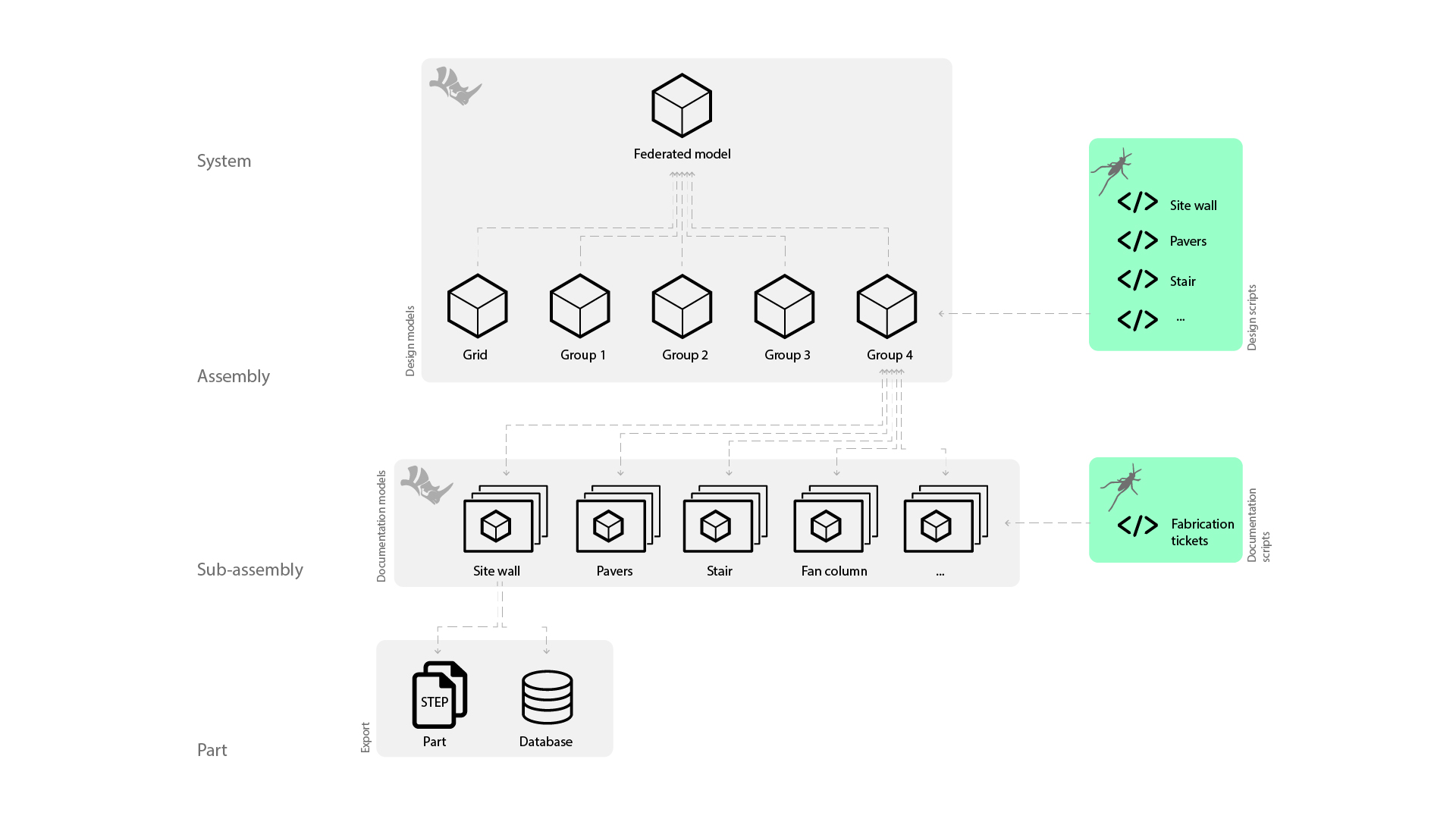
The design model geometry was streamed into separate Rhino models for 2D shop drawings and fabrication tickets. Separate Grasshopper scripts, utilising DraftHorse, generated layouts. Finally, all unique parts were exported as a STEP file using Pancake, while the metadata was exported and managed using an Airtable database.
Where every element, no matter how small, has been thoughtfully and intentionally engineered.
Feature types
The external plaza consists of seven feature types: benches, curbs, fan columns, paving, shopfronts, site walls, and stairs. Through a curved language, each element creates a crafted softness to welcome users. At face value, many of the elements look straightforward. But this is misleading. Taking a closer look reveals their full complexity, where every element, no matter how small, has been thoughtfully and intentionally engineered.
Paving
By far the most significant component of the external plaza is the paving. Featuring large-format pavers, the setout is aligned with the interior lobby tiles. However, despite its apparent simplicity, the design and modelling of the pavers were complex.
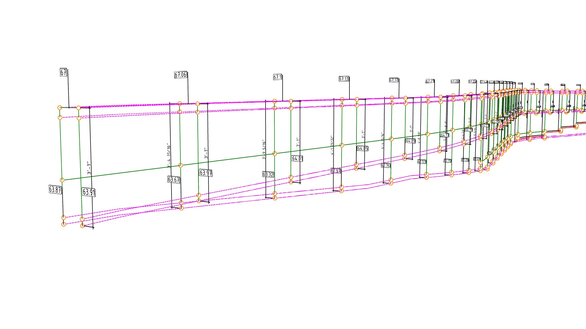
The digital workflow first imported the 2D civil spot elevations into Rhino. Grasshopper was then used to place a leader at each 2D spot elevation, read the Relative Level (RL) of the text, and move the leader to the correct height.
Once the 3D spot elevations were created, the next step was to generate a base surface from the points. Given that there are multiple ways to achieve this, some digital craft was required. One method is to use a Delaunay mesh to generate a series of planar faces. However, while this process is acceptable for topography, it becomes problematic with pavers, as the mesh edges won’t align with the paver joints.
Another approach is to create a surface through points. However, this approach would yield a continuous, double-curved surface and would fail to account for deliberate gradient changes, such as at the top and bottom of ramps. What was needed, therefore, was to split the plaza into subareas based on the paver setout and then create simple, individual surfaces for each area. Lofts were ultimately used to generate the subsurfaces, as they afforded far greater control over surface generation in conforming to intermediate spot elevations.

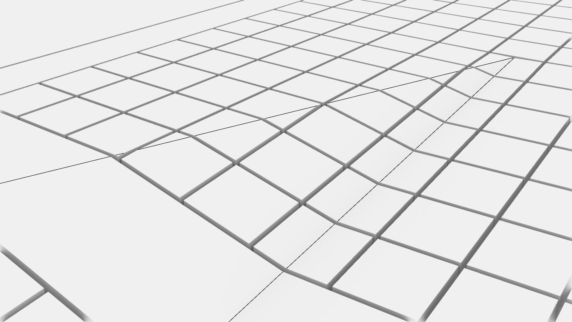
The next step was to subdivide the surfaces based on the paving setout. In general, pavers were planar, except where excessive lippage or design intent required a different solution. Therefore, three different types of pavers were required: planar, warped, and 3D pavers.
Planar pavers
Creating a planar surface from a subdivided surface is a relatively simple geometric process. Once generated, the deviation can be calculated and checked. If the deviation falls within acceptable tolerances, the pavers could be grouped by type with an accompanying key plan. Fabrication tickets were relatively straightforward, requiring only a 2D plan.
Warped pavers
Where planar pavers resulted in excessive lippage, that is, variations in height between adjacent paver edges, these pavers were modified to create a warped top surface to ensure geometric continuity. This adjustment proved somewhat complex as the warped surface needed to be based on the adjacent planar pavers, not the design surface. While the top surface was warped, the base surface of the paver remained planar, so only one side needed CNC milling, reducing cost and fabrication time. These modifications resulted in pavers of varying thicknesses, requiring them to be documented in 3D.
3D pavers
Other atypical pavers needed to be documented in 3D due to the design intent. For example, the curb ramps with tactile indicators were fabricated from a single piece of stone.
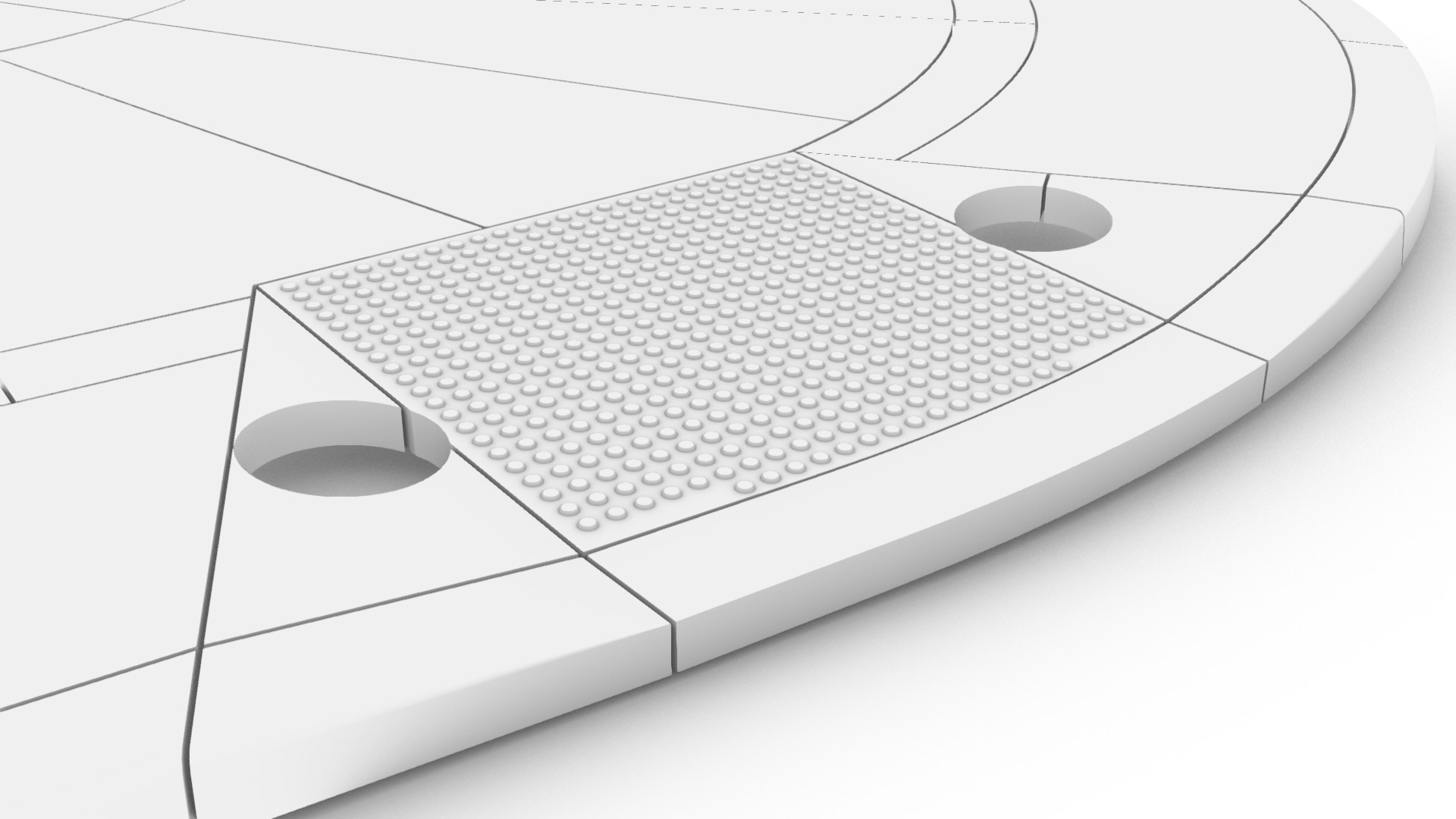
Additionally, some pavers incorporated gradient changes, but the design intent mandated that no joints be used. For example, at the driveway crossover, the cobblestone pavers needed to incorporate the facet, requiring it to be documented in 3D.
Each 3D part added complexity, requiring a unique fabrication ticket and CNC fabrication.
Site walls
The plaza contains eight site walls, which negotiate the change in levels between the stairs, ramps, and the adjacent pavers. The digital workflow was split into two stages. The first Grasshopper script established the wireframe model. Included in this model were numbered set-out points, which enabled the shop drawing sections to be automatically generated at each joint line. The second Grasshopper script referenced the wireframe geometry and created the solid geometry.
Several design requirements made the geometry of the site walls complex. The first is that one side of the site wall typically contained an alternate profile with recessed lighting. This feature was not a simple extrusion but one that terminated in a blended form.

The second was the cove paver at the base of the site wall. Since the pavers were planar, the wall profile could not be a simple sweep; instead, the geometry needed to be modelled from offset surfaces. To further complicate things, the cove paver had different thicknesses in both horizontal and vertical directions.

Finally, the stainless steel handrail required various cutouts and recesses.
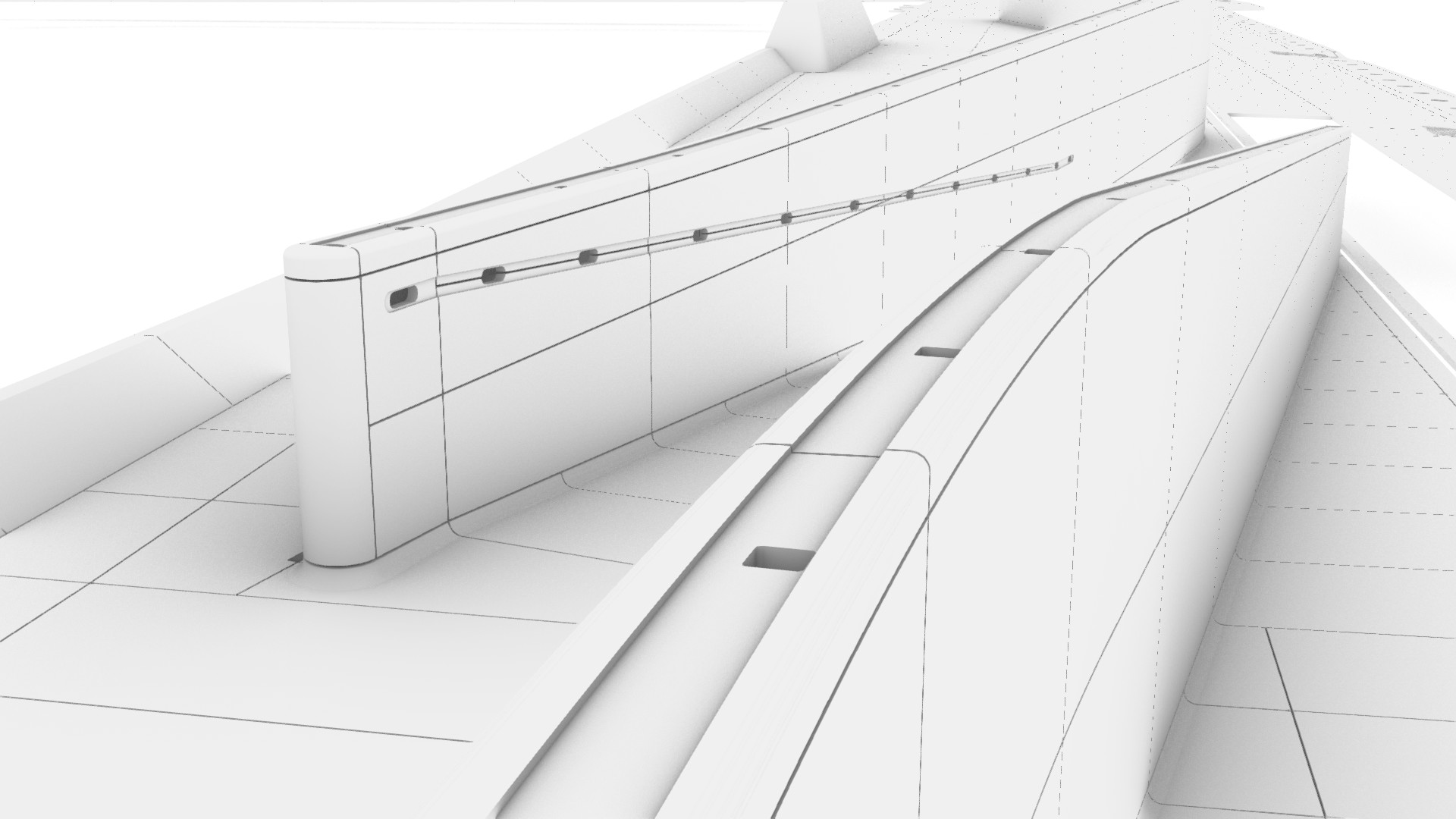
Although accounting for only 6% of the project’s total parts, every site wall piece was unique, requiring every part to be documented in 3D.
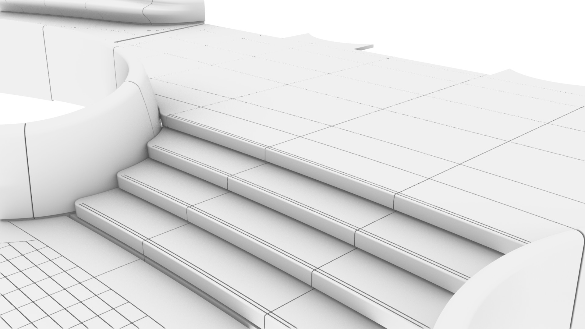
Stairs
The external plaza features six stairs. The main entry to the building off Park Avenue features a curved, organic stair, with a similar organic stair on the west (Madison Avenue). Conversely, the north (E 48th St) and south (E 47th St) stairs are orthogonal, running east-west.
Like the pavers, the stairs featured coved interfaces with the site wall. This design feature added considerable complexity in how the individual parts nested together.


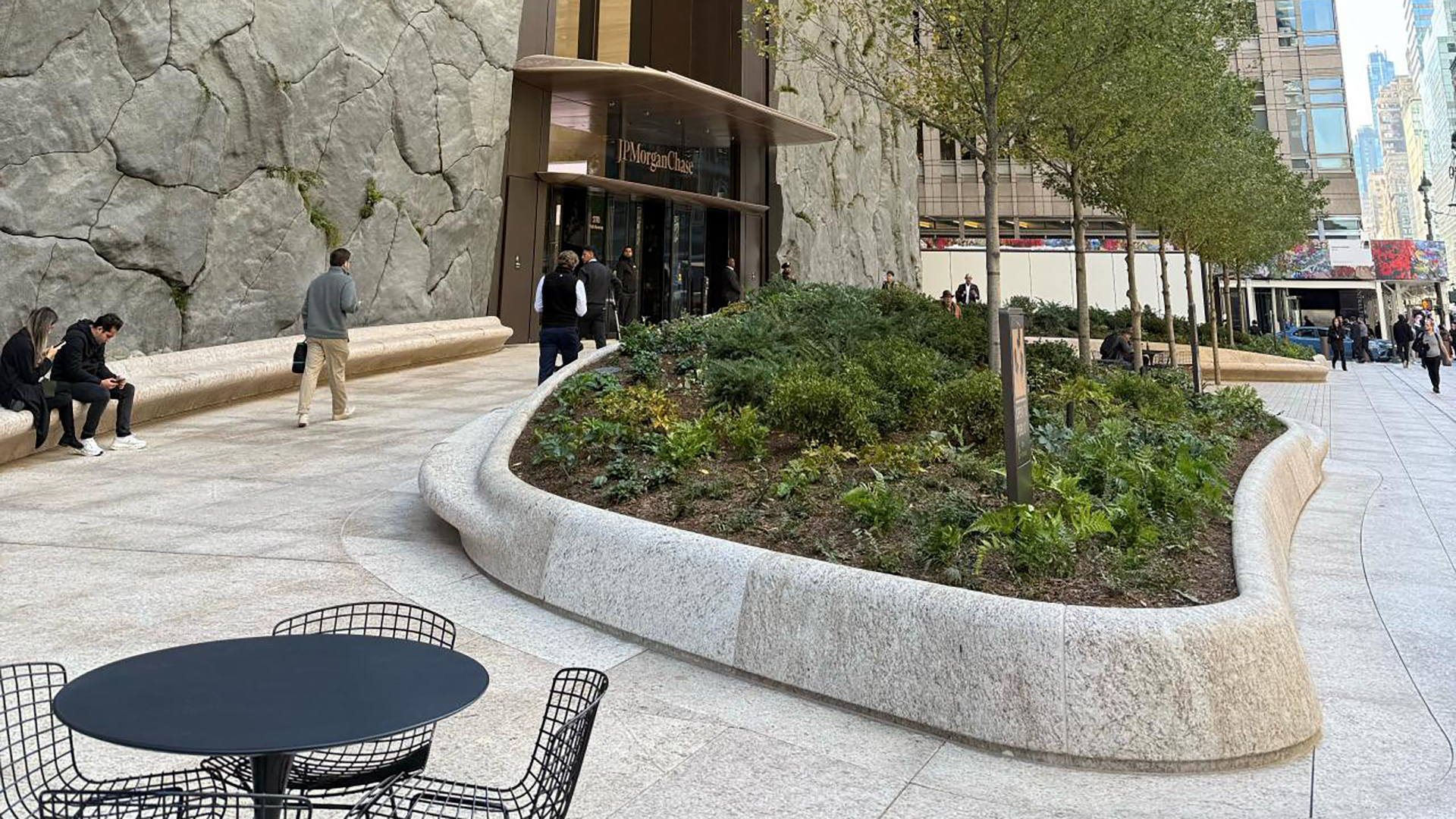
POPS Benches
Along the Madison Avenue frontage is a dedicated Privately Owned Public Space (POPS), a public space owned and maintained by private property owners in exchange for bonus floor area or planning dispensation under New York City zoning policy. Within this space are four sinuous planters with integrated bench seating. Each part was milled from a single piece of stone, with some parts measuring up to 1.6m x 0.8m x 1.2m.


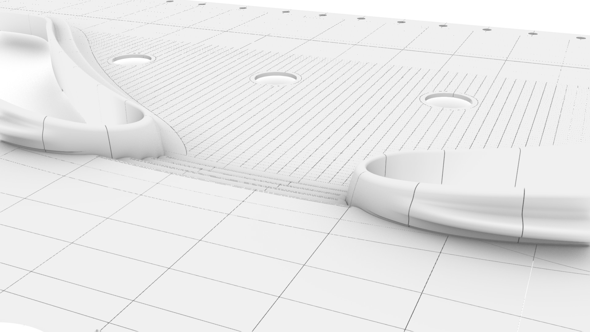

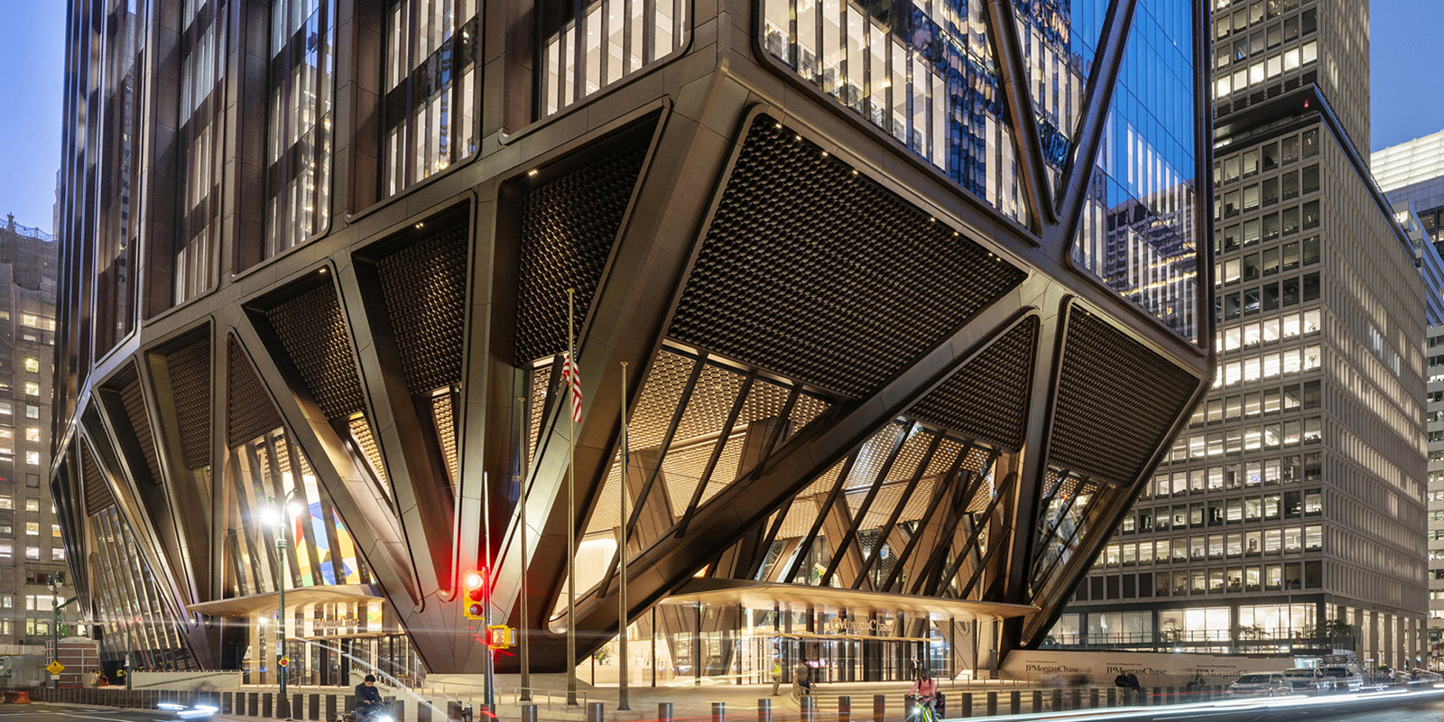
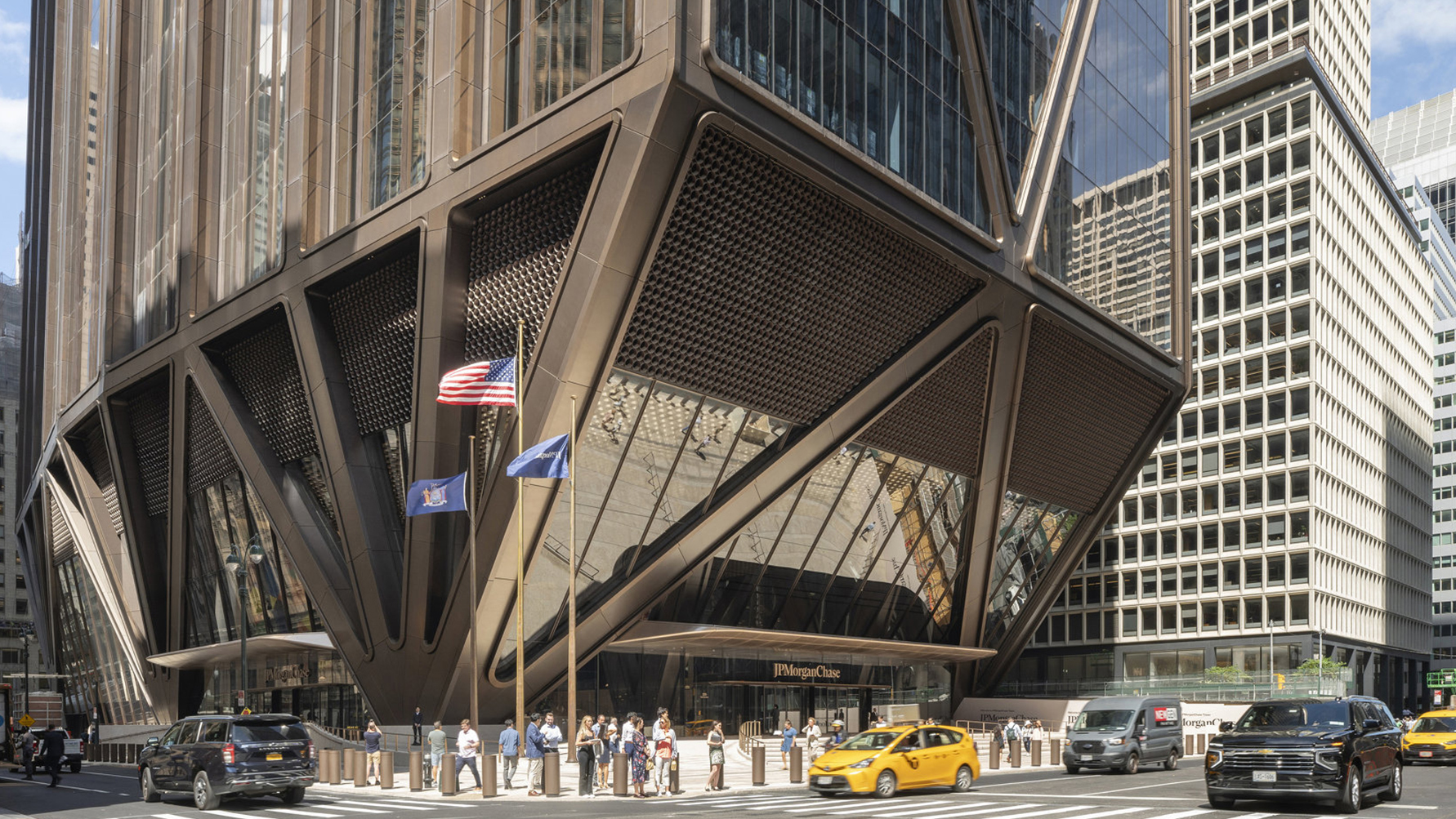
Fan columns
One of the most striking features of 270 Park Avenue is the bundling of its structure into a handful of fan columns at its base, due to the underground train tunnels. At the plaza level, these fan columns are clad in stone. Each part is milled from a single piece of stone, with some as large as 2m x 1.5m.

Curbs
Unlike conventional pre-cast concrete curbs, the curbs at 270 Part Avenue were constructed from stone. Most were simple extrusions that followed the Top of Curb (TOC) line. Geometrically, the profile could not be swept along the path, so the TOC curve was faceted into straight segments for documentation. While most parts were easily documented, curb transitions for ramps required 3D documentation.
Data management
Due to the sheer quantity of parts in the project, data management was critical. Indeed, the external plaza comprises approximately 14,574 individual parts, of which 2,784 are unique. However, as the Pareto principle predicts, the distribution of time and effort was not even. Despite accounting for only a tiny share of total parts, the site walls and stairs took up a considerable amount of time due to their complexity and the high percentage of unique parts.
| Element | Unique parts (#) | Unique parts (%) | Total parts (#) | Total parts (%) |
|---|---|---|---|---|
| Benches | 92 | 3.3% | 92 | 0.6% |
| Curbs | 141 | 5.1% | 339 | 2.3% |
| Fan columns | 56 | 2.0% | 56 | 0.4% |
| Paving | 1,163 | 41.8% | 12,576 | 86.3% |
| Shopfronts | 42 | 1.5% | 42 | 0.3% |
| Site walls | 897 | 32.2% | 897 | 6.2% |
| Stairs | 393 | 14.1% | 572 | 3.9% |
| 2,784 | 100.0% | 14,574 | 100.0% |
To assist the data management process, each part included a part number (type), a location ID (instance), a revision, and other metadata. This data was baked into the geometry using the new out-of-the-box components found in Rhino 8. Data was verified using a Grasshopper utility script that colour-coded parts based on the metadata.


Once the data had been created, it was managed via a cloud-based database, Airtable. This approach has a clear benefit as databases work better with large datasets and can be relational. For example, the part list was linked to the program schedule, which in turn was linked to the project team directory. As a result, data becomes structured and easier to manage.
A File-to-factory workflow
Each part was made from Giallo ornamental granite and prefabricated in Carrara, Italy, by Santucci. Although the project included both ‘2D’ and ‘3D’ parts, all parts were exported to STEP format and accompanied with a corresponding fabrication ticket. The manufacturer could then choose between CNC or manual fabrication. Completed parts were then shipped to New York for installation.
Software limitations
While Rhino excels at handling complex geometry, it has many limitations in 2D documentation. Firstly, Rhino slows down considerably once there are about 20 layouts in the model. Beyond 100 layouts, the file will become too slow to work with. Therefore, just like a BIM model, how the model is broken down should be carefully considered.
Secondly, the RhinoCommon API lacks functionality to programmatically create dimensions associated with Rhino geometry. For example, if Grasshopper is used to create dimensions on a layout (‘paper space’), the dimension length will be inaccurate because it cannot reference the (scaled) geometry in the viewport. Conversely, if Grasshopper is used to create a dimension in the model (‘model space’), the dimension will not update if the Rhino geometry is manually updated. Dimensions, therefore, need to be created in the model and controlled via layer visibility, or they must be manually created on layouts.
Finally, Rhino’s display modes are machine-specific rather than file-specific, which can lead to inconsistent outputs when multiple team members print layouts. For example, if one team member sets up a custom display mode, that setting is saved only on their machine. To maintain graphic consistency, it must be exported so that other users can import it. While this can be managed, it is far from an ideal workflow. In Revit, for example, all visibility graphic settings are saved in the file, ensuring consistency regardless of who prints it.
Conclusion
The external plaza of 270 Park Avenue stands as a remarkable testament to parametric modelling and digital fabrication. Despite its apparent simplicity, the project proved deceptively complex, requiring manufacturing tolerances rather than standard construction tolerances to achieve the crafted softness desired. Two key design decisions fuelled this requirement for high-level geometric precision. The first was the cove paving, which created seamless interfaces with adjacent parts. The second was the continuity of joint lines, which span the entire length of the site. However, by adopting a file-to-factory workflow, the project team ensured geometric precision and enabled the fulfilment of the architectural vision.

Project team
Developer: Tishman Speyer
Design Architect: Foster + Partners
Architect of record: Adamson & AAI Architects
Main contractor: AECOM Tishman
Civil subcontractor: John Civetta & Sons
Stone fabricator: Santucci
Stone setters: Berardi Stone Setting
Digital consultants: Thelen Design Group, Galbraith Design Studio, Parametric Monkey and Slantis
Stone project management: CSCE
Stone consultants: ISCS