

The construction industry accounts for 38% of global carbon dioxide (CO2) emissions.1 And without intervention, climate breakdown and biodiversity loss will continue to accelerate. In response to this crisis, architects worldwide have begun signing up for ‘Architects Declare‘. Launched in 2019, Architects Declare is a global movement aimed at reducing both embodied and operational resource use. Therefore, it comes as no surprise that since its launch, the Architecture, Engineering and Construction (AEC) industry has seen a significant uplift in mass timber buildings due to its high carbon sequestration value. However, this case study explores in depth another benefit of using mass timber, the ability to adopt Design for Manufacture and Assembly (DfMA) and to achieve this at scale via automation.
Mass timber
Mass timber, sometimes referred to as engineered wood, is ‘a range of composite wood products that utilise state-of-the-art technology to bind or fix the strands, particles, fibres, veneers or boards of wood together with adhesives, fasteners or other methods of fixation.’2 The mass timber family includes Glue-Laminated Timber (GLT), Laminated Veneer Lumber (LVL), Nail Laminated Timber (NLT), Dowel-Laminated Timber (DLT), and Cross-Laminated Timber (CLT). Of these products, CLT and GLT are among the most well-known.
In addition to being a natural and renewable material, the great advantage of wood is its high carbon sequestration value. Growing trees sequester carbon dioxide from the atmosphere, storing the carbon. In fact, about half the dry weight of a tree is carbon. This carbon remains locked up for the life of the wood, even when used for building products, helping offset global greenhouse gas emissions.3
Another benefit of mass timber is the potential to rethink the traditional construction process. Mass timber has clearly defined structural limits, which means it is possible to know its floor span and thickness in advance. While it doesn’t eliminate the need for professional structural analysis, it does mean the bulk of it can be automated. This opens up possibilities to shift from a project-based approach, where each solution is bespoke, to a product-based approach, which uses mass customisation. Additionally, mass timber can close the gap between digital technologies and the physical construction process by enabling a file-to-factory digital fabrication process.
Background
Parametric Monkey was commissioned by the Timber Development Association (TDA) to work with a team of experts to explore the potential of a ‘Post and Plate’ CLT construction method. The work was supported by funding provided to Forest and Wood Products Australia (FWPA) to administer the National Institute for Forest Products Innovation program by the Australian Government Department of Agriculture, Water and Environment (DAWE) and the Victorian Government.
Why Post and Plate? Quite simply, a post and plate system has no beams, simplifying MEP services and allowing for either higher floor-to-floor heights or more floors (and therefore more Gross Floor Area). To realise the potential of the post and plate system, new mass timber installation concepts needed to be developed, which satisfied safety and building regulations. The team included Andrew Dunn (TDA), Prof Perry Forsythe (UTS), and Parametric Monkey, with the support of XLAM and Rothoblaas. A nominal 30m x 20m (600m2) building floor plate was chosen, and together, the team explored various options to achieve a fast, efficient, reliable and cost-effective floor cycle.
Two viable solutions emerged, which came to be known as ‘Centre supported infill‘ and ‘Edge support‘. A third system was also modelled and used as a benchmark. Known as ‘Band beam‘, this is a similar system to that used in Brok Commons, an 18-storey student housing complex at the University of British Columbia in Canada. When it was opened in 2017, it was the tallest mass timber structure in the world. The 9-person install crew averaged 2+ floors (930m2) /week. However, this system uses a traditional band beam and therefore doesn’t have the benefits that the post and plate system afford.
Digital process
From the project’s inception, the team recognised the importance of having a 4D animation to simulate the construction logic to identify problematic installation issues and engage industry experts in the feedback process. These requirements facilitated the need to go beyond what is typically produced during the traditional digital process.
Building Information Modelling
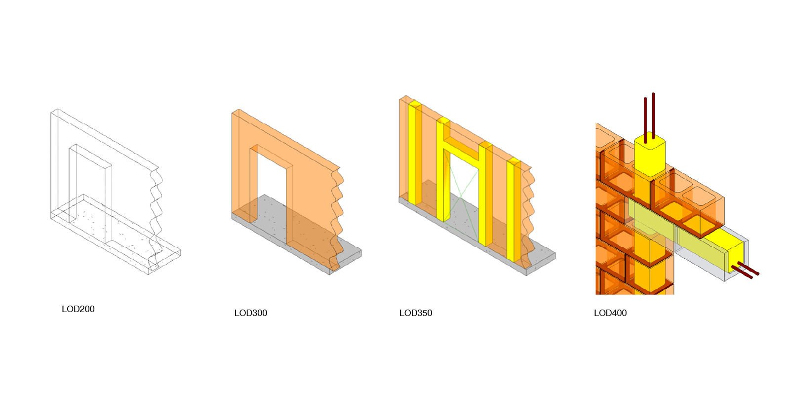
Building Information Modelling (BIM) is a process for creating and managing all information on a project. A BIM model can come in a variety of resolutions based on its Level of Development (LOD), from LOD100 (generic representation) through to LOD400 (fabrication). Once the building is complete, the BIM model is updated to reflect the as-built conditions and is known as LOD500.
BIM design model
During the design process, an architect typically authors the BIM model to LOD300, in say Autodesk Revit or Graphisoft ArchiCAD. At this stage, ‘the quantity, size, shape, location, and orientation of the element as designed can be measured directly from the model without referring to non-modelled information such as notes or dimension call-outs.’5 This means that the nominal width of CLT floors and walls should be shown for our prototypical CLT project, but not necessarily the layup. The panelisation may also be shown, but unlikely the mechanical connections.

BIM fabrication model
Once the BIM model passes over to the manufacturers, it may continue to reside in the same BIM software or be imported into fabrication-specific software, such as Dassault Systems Solidworks, Autodesk Inventor or Trimble Tekla. Conversely, Hsbcad or Cadwork is typically used for mass timber projects. In any case, the model will generally evolve to LOD350 or LOD400, depending on the requirements of the main contractor.
However, while a BIM model explains what to build, it doesn’t explain how to build it.
LOD350 is considered sufficient for trade coordination. However, over recent years, many main contractors have begun requesting LOD400 fabrication models for ‘enhanced’ coordination. Intuitively, one would assume the higher the LOD, the better the model, but this is not always the case and can be counter-productive.
In theory, the LOD400 model should contain every element to fabrication tolerances. For our project, this would include CLT panels with rebates and pre-drilled holes ready for CNC machining, as well as the numerous mechanical fixings. However, while a BIM model explains what to build, it doesn’t explain how to build it.
Virtual Design & Construction (VDC)
Virtual Design & Construction (VDC) is a term that refers to the digital planning of all aspects of a construction project. The VDC process typically includes cost information, 4D phasing and site logistics, such as hoarding and crane locations. Some may argue that this is still, in fact, BIM, just with a construction focus.
With a conventional construction system, the construction phasing Gantt chart is mapped to the BIM model to produce a 4D animation. The result, however, is building elements ‘magically’ appearing at key milestones. Since the building is mostly traditional build, this doesn’t tend to matter too much. So while the process gives some indication about how to build it, to get the full picture, one needs to adopt a Design for Manufacture & Assembly approach.
Design for Manufacture & Assembly
Design for Manufacture and Assembly (DfMA) is a design approach that includes how the element is manufactured and assembled. In other words, it tells you not only what to build but how to build it. Unlike conventional construction, DfMA can be considered a Modern Method of Construction (MMC) as it typically uses prefabrication, pre-assembly, design standardisation and automation.
Limitations of existing simulation software
Existing off-the-shelf software entrenches the siloing of the design phase from the simulation phase. In the Autodesk ecosystem, buildings are modelled in Revit or Inventor and then simulated in Navisworks. Similarly, in the Dassault Systemes ecosystem, buildings are modelled in Catia and simulated in Delmia. In either case, the digital process adheres to the waterfall project-management system, where the model is ‘pushed’ to the simulation software once the design is complete. This is a missed opportunity, as the simulation acts merely as a visual tool rather than as a positive feedback loop to improve the design.
This is a missed opportunity, as the simulation acts merely as a visual tool rather than as a positive feedback loop to improve the design.
Additionally, while there is some bi-directionality synchronisation between the various software, animations are generally keyframed. In other words, an element’s location or visibility is marked relative to its time in the timeline. If only visibility parameters need to be modified, such as for conventional construction systems, these can be mapped from project management software such as Bentley Syncro or Oracle Primavera. However, if an element needs to move, such as a crane, the digital model needs to be rotated, and a new keyframe added. And this needs to be repeated for every move of every element. Needless to say, this is an incredibly time-consuming process and is why we typically only see visibility-based animations, which exclude movement.
Towards DfMA
As an alternative to siloing the design phase from the simulation phase, we can converge the two phases through the automation of keyframes. By capturing and codifying the DfMA logic, each element knows its final state and how it get there – the crane paths, the rotations, and the sequencing. This technique has been used extensively within robotic fabrication but has yet to become mainstream with buildings. It is, however, not without its technical difficulties. Not because of the intricate digital ‘choreography’ – that can be managed – but due to the software in which it occurs.
Technical constraints
Most BIM authoring software has entrenched ways that it believes buildings should be conceived. Take, for example, a column in Revit. The column has a bottom constraint (Level 0) and a top constraint (Level 1). Being parametric, once the RL of Level 1 is modified, the column flexes accordingly relative to the updated constraints.
However, if we wanted to rotate the column to show it on the ground, ready to be installed, the out-of-the-box (OOTB) functionality doesn’t enable this. The top constraint would override the rotation. The column could tilt and be ‘stretched’ in the process, but it couldn’t lie flat on the ground. However, certain workarounds can be adopted to enable this functionality. By creating a custom family, a rotation parameter can be embedded, liberating it from its top constraint.
But this is just one of the technical hurdles that need to be overcome in conventional BIM authoring software. Many elements within Revit require hosts. For example, a column is hosted to a level; delete the level, and the column is also deleted. This limitation means that when simulating an element’s movement, care must also be taken to move the host, which often isn’t possible or desirable. In this case, the element must be decoupled from the host altogether. Again, the challenge here has more to do with the software in which it is being performed than the codification process.
Automating DfMA mass timber buildings
The three options – Band beam, Centre supported infill and Edge support – were each modelled in-situ with Revit. Phasing parameters were then populated, and Dynamo used to codify the install sequence movements. Once complete, the Dynamo graph was run in periodic mode, which automated the re-execution of the graph at pre-defined intervals, effectively creating a custom animation timeline directly within Revit. Detailed animations were done in McNeel Rhinoceros 3D using snapshots.
Benchmark: Band beam
The band beam system features an 8.2m x 6.8m grid, haunched columns, Peri Gridflex formwork, and screwing. Install requires a 10-person crew and tower crane. The floor cycle takes 15 hours and involves five sub-cycles:
- Setup Gridflex formwork
- Column lifting
- Band beam lifting
- Cross panel lifting
- Jointing.
Option 1: Edge support
The edge support system features a 6.6m x 3.3m grid, Rothoblaas Pillar connector, temporary framing and CHS couplers. Install requires an 8-person crew and tower crane. The floor cycle takes 14.3 hours and involves four sub-cycles:
- Column lifting
- Bearer/tie/prop installation
- Panel lifting
- Jointing.
Option 2: Centre supported infill
The centre-supported infill system features a 6.2m x 6.8m grid, Rothoblaas Spider connector and the use of two fabrication bays. Install requires a 12-person crew, a mini crane, and a tower crane. The floor cycle takes 11 hours minimum and involves four sub-cycles:
- T-table fabrication in bays
- T-table lifting
- Infill panels lifting
- Jointing.
Deliberations
In an industry where time is money, often savings made during the construction phase can dwarf savings made through value engineering the design. Crane hire, temporary site offices, insurances, etc. all add up for each extra day or week it is needed. It, therefore, makes sense to optimise it. And this is what DfMA does.
The 4D animations shown above were used not merely as a tick box BIM deliverable but as an integrated digital tool to improve the design. They went beyond BIM to inform us not only what to build but also how to build it. And the results speak for themselves. The centre-supported infill option has a floor cycle approximately 25% faster than the benchmark band beam option. Additionally, the floor-to-ceiling height is 340mm higher without needing beams, improving amenity and simplifying MEP servicing.
Now should this be done in Revit? It depends, but probably not. Revit really wasn’t designed to handle fabrication-level models, nor was it designed to handle 4D animations. As illustrated above, it can be achieved, but there are certainly scalability issues. However, Revit’s shortcomings shouldn’t be used as an excuse to hold us back. The concept of automated keyframes is sound. The issue is only the environment in which it is generated. Alternative approaches could have included using Rhino.Inside.Revit to extract Revit geometry so that elements were decoupled from their host, significantly simplifying the complexity of the task. Or even automation directly in real-time animation software.
Conclusion
This case study explored the benefits of using mass timber together with DfMA. It highlighted how mass timber construction logic could be captured and codified to achieve automation at scale. Moreover, it pushed the limits of Revit just that little bit higher by using Dynamo to drive 4D construction sequencing animations directly within Revit. Some architects may argue that DfMA is outside of their domain. But if we are serious about reducing both embodied and operational resource use, we must be serious about how our buildings are constructed. And the best way to achieve this is to visualise not only what we are building but also how we are building.
References
1 Neill, P. (16 Dec 2020). Construction industry accounts for 38% of CO2 emissions. In Environment Journal.
2 Nextimber. (2022). Sustainable structures: Why mass timber is the future of construction.
3 Timber NSW. Timber in the Carbon Economy.
4 The Associated General Contractors of America Inc. (Dec 2021). Level of Development (LOD) specification part 1 & commentary: For Building Information Models and Data, pp.85-87.
5 The Associated General Contractors of America Inc. (Dec 2021). Level of Development (LOD) specification part 1 & commentary: For Building Information Models and Data, p.16.


1 Comment
Dru Farnham
I love this. These animations provide a lot of insight just as it was needed in my architectural drawing class at LATTC. I need to place a column, beam and strut system for a multi-unit using mass timber. Thank you