
This case study presents how a manufacturer’s modelling and shop drawing processes can be automated using mass customisation. Via a process known as knowledge elicitation, it demonstrates how tacit knowledge can be extracted and codified into an algorithm. This shift from standardisation to systemisation enables a digital workflow that can generate custom output based on project-specific inputs. The result is a workflow that is highly flexible, scalable and, in this particular instance, up to 40 times quicker than manual drafting.
Background
Many building systems within the Architecture, Engineering and Construction (AEC) industry cannot be fully standardised due to project-specific requirements. For example, spatial layouts and floor-to-floor heights will inevitability vary across projects. This variability can become a bottleneck to the shop drawing production process, as each project must be individually documented. To address this problem, Parametric Monkey was commissioned by our client to automate the modelling and documentation of their ceiling system.
The client was using Autodesk Inventor but wanted to migrate to Autodesk Revit due to the automation afforded by Dynamo. Previously, the shop drawing process would take around two weeks for a typical project modelled in Inventor. However, as this case study will demonstrate, by automating the process in Dynamo, we were able to reduce this to around two hours – approximately 40 times faster compared to manually drafting.
Standardisation & mass production
Most AEC manufacturers will offer standardised products. These products are pre-defined, dimensions set, connections resolved, performance and regulatory compliance undertaken, and the fabrication process and supply chain locked in. This standardisation ensures consistency across projects and helps eliminate errors in the production process. Moreover, if every product is identical, say a door, these products can be mass-produced. In mass production, the product only needs to be documented once; therefore, automation offers little benefit.
Systemisation & mass customisation
However, most building systems cannot be identical due to project-specific requirements. While much of the standardisation process remains relevant, the system must flex and adapt to accommodate different project requirements. This is where mass customisation comes into play. Mass customisation embeds the standardised logic into an algorithm, which can generate custom output based on the project-specific inputs. This systemisation combines the low unit costs of mass production processes with the flexibility of project-specific customisation. It also affords to possibility to adopt digital fabrication and Modern Methods of Construction. Unlike mass production, there is an enormous benefit in automating a mass customisation process, as will be shown.
The system
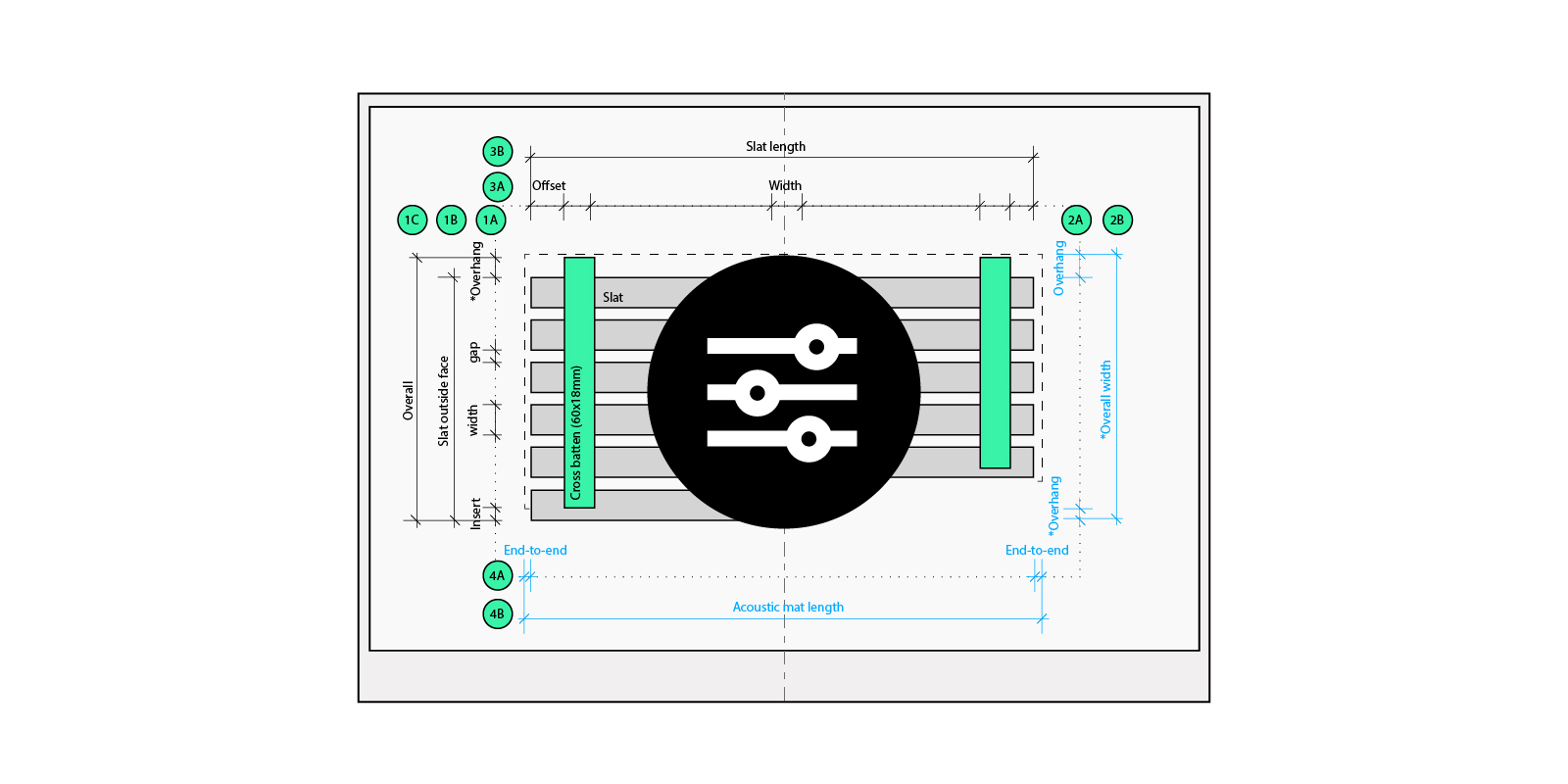
The ceiling system offers five slat profiles, each with predefined dimensions. Additionally, there are two different backing options. Depending on the slat type specified, the set-out and relationship of these elements vary. Therefore, there are ten different system configurations, excluding material finishes, which can be easily captured in typical details.

Knowledge elicitation of system rules
This type of information is known as explicit knowledge, as it is easy to articulate and codify. We know what needs to be done and can implement it. However, there is also knowledge, which cannot be easily articulated, and this is known as tacit knowledge. For example, you might rely on rules of thumb or intuition to solve project-specific problems. You know that the answer or output is correct, but you may be unable to articulate why.
Knowledge elicitation is the process whereby a knowledge engineer (Parametric Monkey) works with a domain expert (the Client) to extract tacit knowledge to codify it into an algorithm. What does this process specifically entail? It means asking lots of questions: Why did you do that? What happens in this situation? What if this happens? How would you resolve that? Once we have the answer, rules can be developed and embedded into the algorithm.
Documentation of system rules
The outcomes of the knowledge elicitation process were also documented in a user manual. The purpose of this was two-fold. Firstly, it provided the client with all the necessary information to use the scripts. For example, what Revit version was supported, what third-party package versions were required, and possible solutions to problem troubleshooting.

Secondly, the document acted as a return brief. As rules were unearthed, the documentation captured all of this information. If the scripts produced a result we weren’t quite sure was correct, we could go back to the rules to identify if the rules needed to change or if the output was as expected. This was the only way the system’s complexity could be captured and easily communicated with the client.
Development process
The process was a phased engagement, with each phase adding improved functionality. The initial phase consisted of several Dynamo workshops introducing the client’s drafting team to Dynamo. Instead of generic content, the workshop went through step-by-step the applied process of automating the modelling of the system. No atypical scenarios were considered, just simple rectangular layouts. The client understood that some manual interventions would still be required.
The second phase focused on documentation. This phase included generating the required Revit content, such as title blocks, shared parameters, view templates, etc., and the Dynamo automation. Again, the automation was designed to accommodate simple rectangular layouts.
The third phase focused on improved functionality to reduce the amount of manual intervention needed and an improved user experience.
Dynamo graph overview
When adopting automation, it is tempting to develop one master definition that does everything. The user then has to press a single button, and everything is done. However, this approach is far from ideal. This is because we tend to imagine best-case project scenarios – simple and uniform requirements without any complexity. The reality, however, is that every project has its idiosyncrasies. Unless the script can factor in every known fringe case that could occur, then the output is either all or nothing.
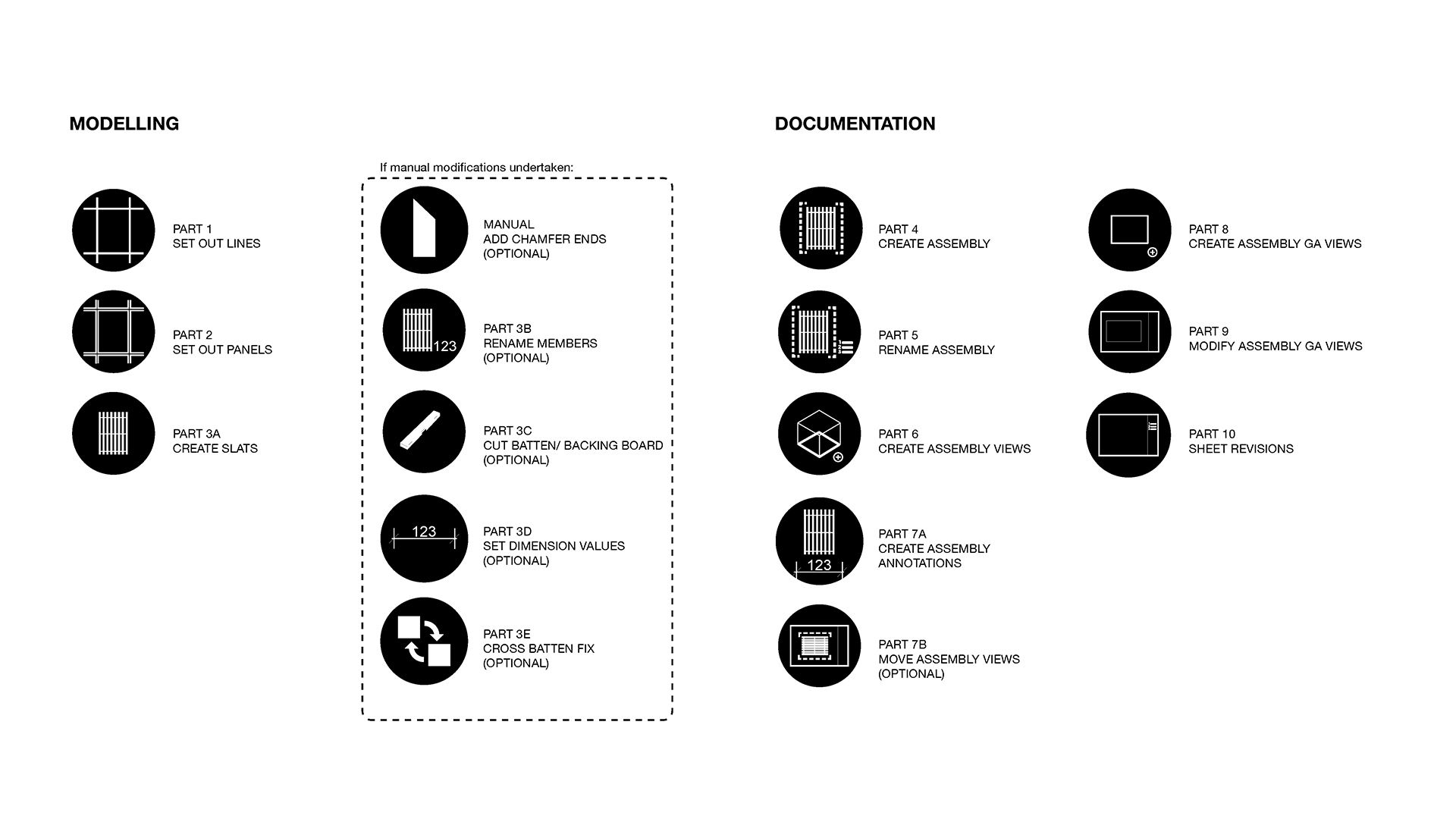
The challenge is not to simplify the design but rather to design a flexible automation process. We achieve this flexibility by creating modular code with clear breakpoints. This structure allows manual intervention, if needed, and ensures progressive output. So what does this mean exactly? Basically, the Dynamo workflow is broken down into multiple sub-routines, with each part focused on a single aspect. Parts 1 to 3 focus on generating the model. Whereas Parts 4 to 9 focus on documentation. If some manual intervention is needed, utility scripts (Parts 3B – 3E) are provided to maintain logic and consistency.
Automated modelling
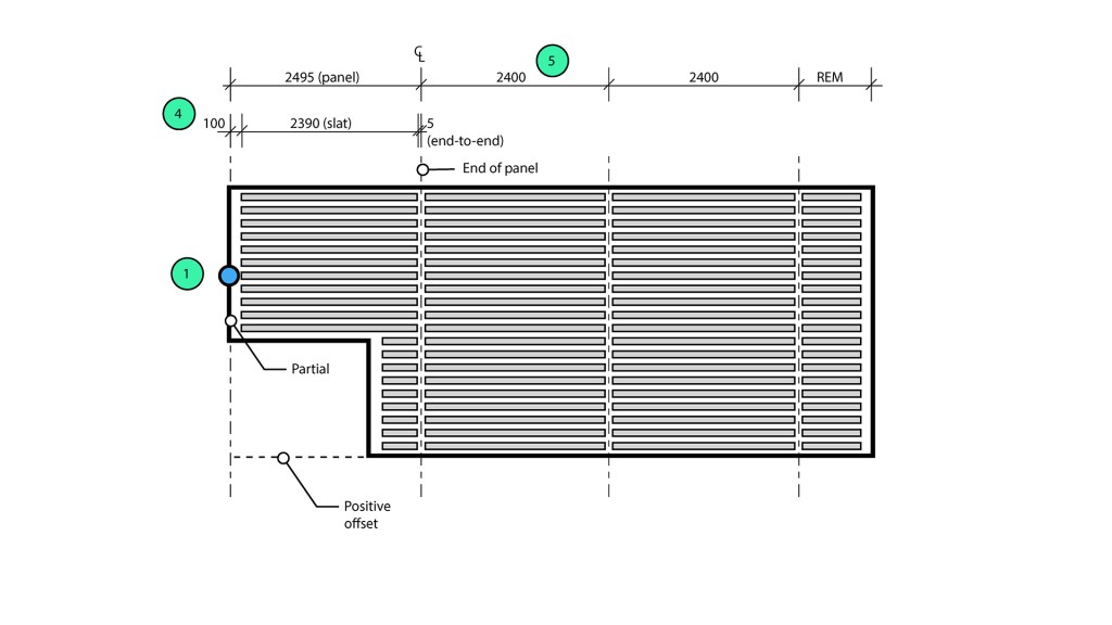
Part 1 – Setout lines
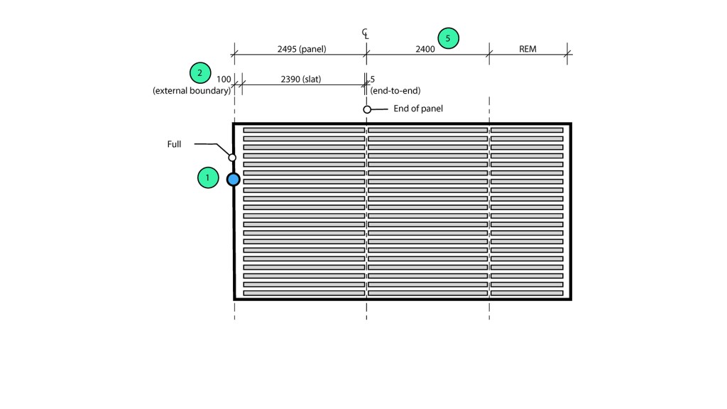
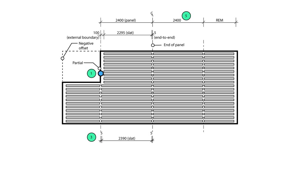
The first step generates the set-out lines based on a set-out point (generic annotation) and the preferred slat orientation. The output is a series of detail lines representing the panel centrelines. Once created, the user can manually modify the lines to override the default panel sizes.
The panel width is calculated based on the slat type, whereas the length is based on the maximum slat length. However, this is not a simple 2D array, as the set-out point is a guide rather than an absolute. In the latitudinal axis, the longitudinal lines must be shifted to ensure the perimeter gap is equal on both sides.

In the longitudinal axis, the latitudinal lines need to be shifted to accommodate the perimeter gap. The shift amount depends on the location of the set-out point relative to the perimeter boundary.

Part 2 – Set-out panels
The second step is to reference the centreline geometry and create the panel zones (filled regions). While this step could have been included in Part 1, this would have meant the user would need to modify multiple elements (detail lines and filled regions) if they wanted to change the default panel sizes. Separating this into two scripts means users can change the set-out with minimal manual interventions.
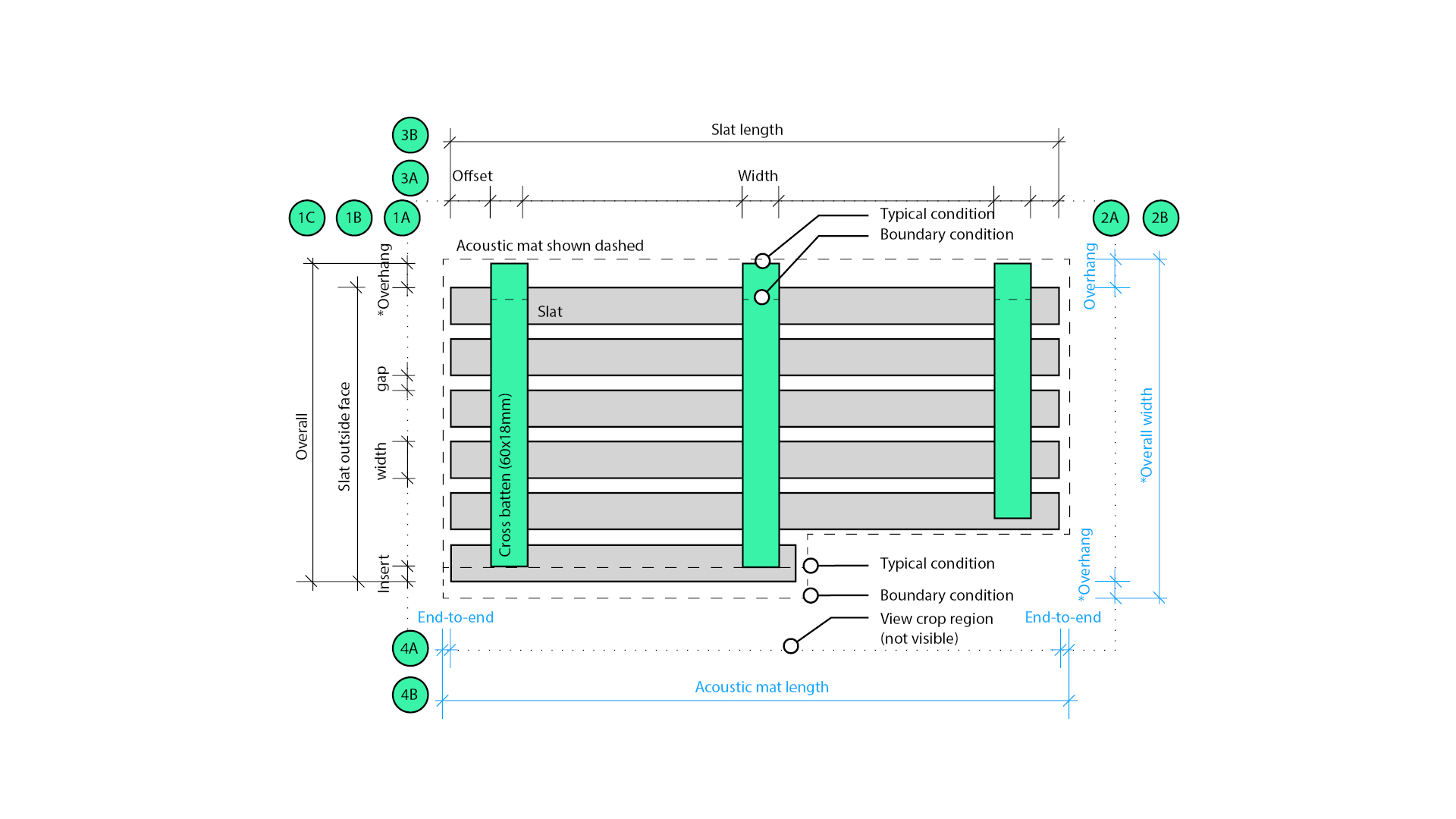
Part 3 – Create slats
The third step is the most complex in the workflow and uses the panel zones (filled regions) to generate the entire ceiling system.
The slats are created via a line-based structural framing family. While the latitudinal set-out of the slats is relatively straightforward, the start and points of the slats must vary to accommodate different end conditions:
- Slats perpendicular to an external boundary are pulled back 10mm by default.
- Slats perpendicular to an internal boundary are pulled back 10mm by default.
- Slats not perpendicular to an external boundary are pulled back a minimum of 10mm by default.
- Slats not perpendicular to an internal boundary are pulled back a minimum of 10mm by default.
- End-to-end gaps are 10mm by default.
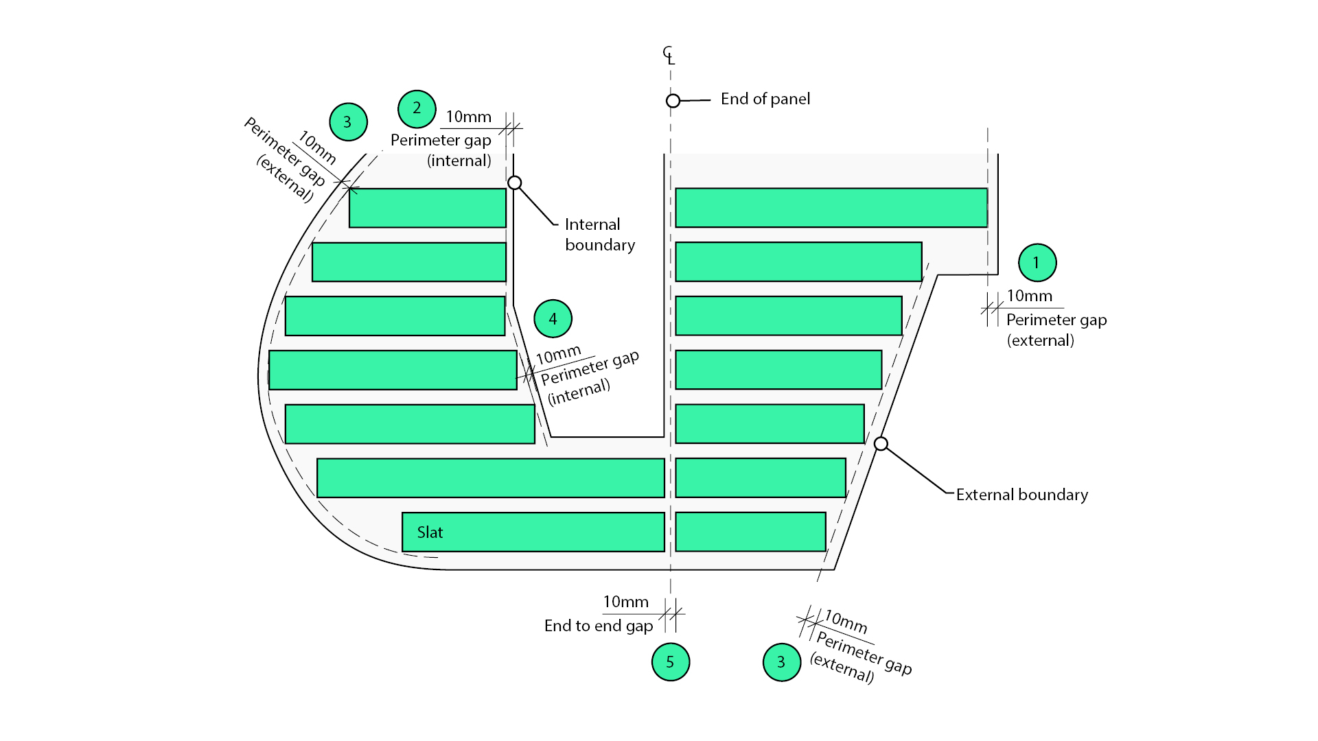
Similar rules for the other elements were also unearthed and encoded into the algorithm.
Automated documentation
Part 4 – Create assemblies
Once all elements have been created, the next step is to group them into an assembly to be documented. Revit automatically calculates unique assembly types and places assembly instances where applicable. Note that once created, assemblies behave differently to model groups, and any manual modifications will make a new assembly type rather than propagating the changes to other assembly instances.
Part 5 – Rename assemblies
The fifth step in the workflow renames the assembly types in the Project Browser. Additionally, each assembly member’s mark value is updated to match the assembly name. For example, slats are prefixed with “S-”. Again, this step has been separated to enable the assemblies to be renamed multiple times if necessary, without the need to keep recreating the assembly.
Part 6 – Create assembly views
The sixth step in the workflow is to create assembly views. The script generates a plan, section, schedules, and the corresponding sheet for each assembly type. Viewports are then placed on the sheet and rotated as necessary. Element-specific schedules are used instead on a combined parts list to enable the maximum assembly size to be scheduled.
Part 7 – Create assembly annotations
Once the assembly views have been created, the next step is to add annotations. Cross battens are tagged in plan, and the slats tagged in section. Dimensions are also added. Individual part sizes are available via the schedules.
If the viewport position on the sheet needs to be updated, Part 7B can be run. This step will move all the assembly viewports based on the layout inputs and may be run multiple times.

Part 8 – Create assembly GA views
This step updates the main General Arrangement (GA) view. Since the view and sheet viewport already exist in the Revit template, the script updates the crop region and centres the viewport on the sheet. The sheet number is also renamed. Assembly types and their quantities are automatically populated in the assembly schedule.

Part 9 – Modify assembly GA views
The final step is to tag the assemblies and add overall dimensions to the GA plan.

User experience
The golden rule of good User Experience (UX) is that things should be self-evident or intuitive, or as some call it, ‘don’t make me think’. When undertaking usability testing with the client, we realised that referencing Revit inputs for the Dynamo inputs was slow and cumbersome. The user had to select a single element, isolate by category, select all the elements, reset the view and then repeat the whole process for the following input. After witnessing this, we amended the script so that the user simply selects everything, and the script does the filtering under the hood. In other words, we designed out the problem to reduce frustration and improve usability.
Another rule for good UX is to provide clear feedback. Since the scripts were initially developed for Dynamo 2.6, Dynamo Player provided limited feedback if something didn’t work. For example, the boundary may not be closed, so the system cannot be generated. Although we had included error messages in the Dynamo Players outputs, they weren’t immediately apparent to users. To address this issue, we improved the UI by adding simple modal Windows messages to give users clear and immediate feedback.
Conclusion
This case study explored the benefits of using mass customisation to automate the shop drawing process. It highlighted how tacit knowledge could be captured and codified into an algorithm to achieve automation at scale. Such approaches enable AEC organisations to move beyond simple standardisation and mass production and toward systemisation, where knowledge is machine-readable. Moreover, it showed such an approach’s enormous time benefits.
To learn how Parametric Monkey can help your organisation on a path of digital transformation, drop us a line and discover how we can help your organisation do better things.