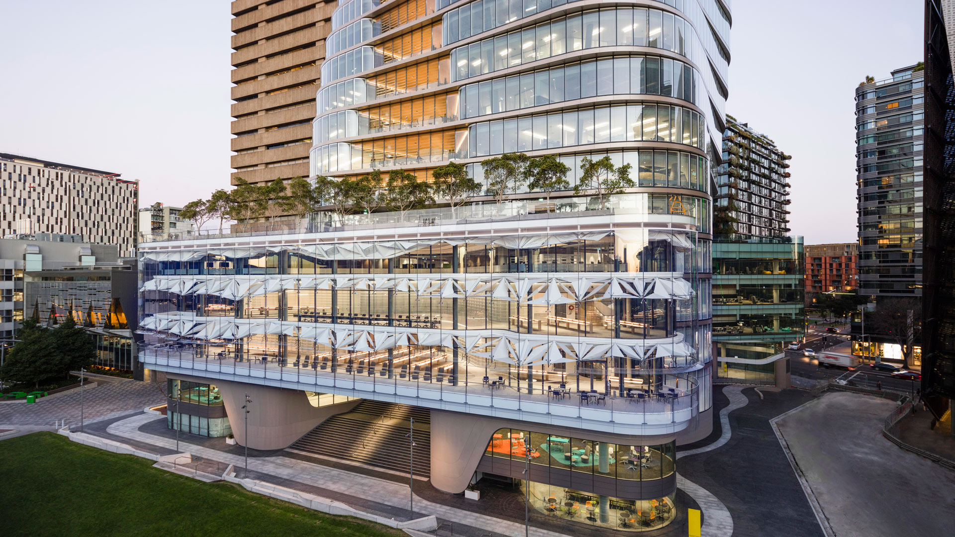

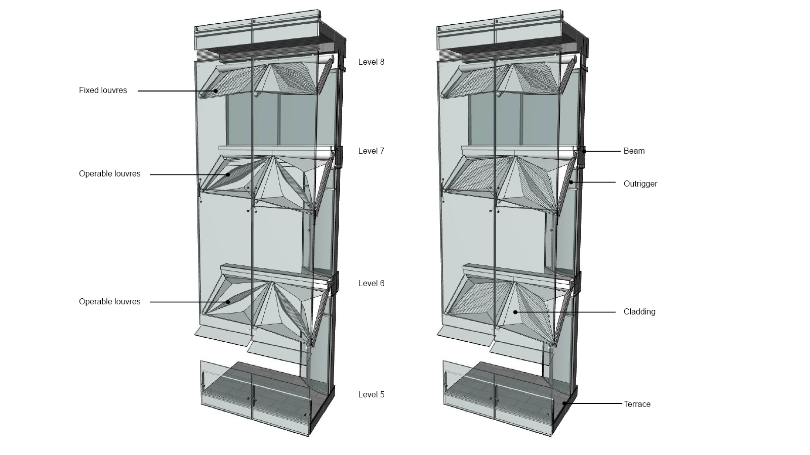
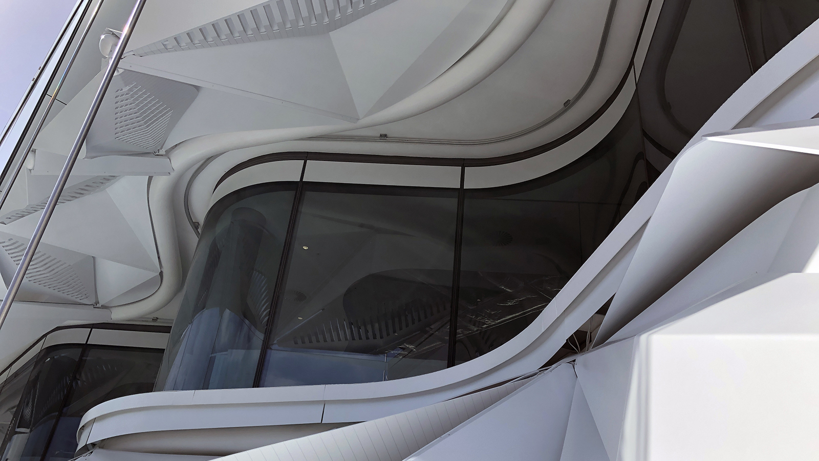
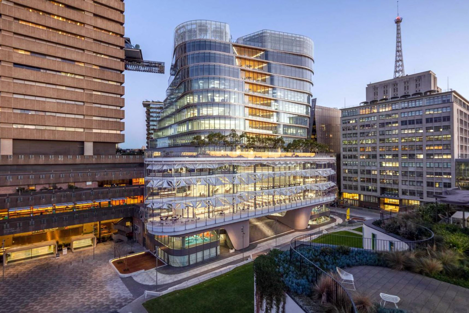
This case study will present the UTS Central project as an exemplar of how an architect’s design intent can be maintained through the use of material-specific design solutions, parametric modelling and digital fabrication. The project is a striking 17-storey, glass-encased building which forms the final project of the University of Sydney’s (UTS) City Campus Master Plan. Parametrically derived via a set of rules, the sun shading system regulates solar access into the library’s reading room. The system is manufactured primarily from folded aluminium components. Each of the 108 unique bays consists of a louvre, 64 of which are operable, with fixed cladding on either side.
Introduction
The Architecture, Engineering and Construction (AEC) industry is one of the least digitalised industries across the board. The much-cited McKinsey report claims that large projects typically take 20 per cent longer to finish than scheduled and are up to 80 per cent over budget.1 While the industry has made inroads with the adoption of Building Information Modelling (BIM), buildings today are still mostly manually constructed. UTS Central addresses this dynamic through the exploration of design-to-fabrication workflows known as ‘Digital Fabrication’.
Early Contractor Involvement
TILT Industrial Design was engaged by the contractor Richard Crookes Constructions (RCC) to provide advice in an Early Contractor Involvement (ECI) process. TILT worked closely with the architect FJMT to create a design model and specification. When combined with the architect’s tender documentation, these documents enabled the contractor to go to tender. Confirming feasibility, approximating budget and an overall methodology for the project. Upon winning the tender, TILT commissioned Parametric Monkey to provide parametric modelling and design-to-fabrication services.
Prototype
An initial 1:1 prototype was undertaken to test both visual and performance-based criteria. Since none of the bays were identical, a mean was prototyped. This mean represented an average of the conditions that were foreseen. The prototype, along with other smaller mock-ups, enabled material-specific feedback to be embedded into the final design.
A File-to-factory workflow
Early in the design process, the design team identified significant benefits that digital fabrication could bring to the project. The proposed file-to-factory workflow entailed automatically unfolding each 3D element to generate 2D shop drawings and nesting patterns for laser and water cutting. This required a cognitive shift away from conventional BIM software, to more manufacture-based software. As Day explains, current BIM methodologies are insufficient:
Building Information Modelling was seen as an advance on old 2D systems because the 3D model could generate all the drawings legally required with co-ordinated updates when edited… However, and there really are no two ways of saying this, all the BIM systems currently on the market were never designed to drive a digital fabrication process, to actually generate the GCODE that runs CNC machines. 2
Limitations of BIM
Put another way, BIM helps digitalise the documentation but fails to address digitalising construction. In order to drive Computer Numerical Control (CNC) machines, design models would have to be created with a much higher level of detail and accuracy. Today’s BIM tools, such as Autodesk Revit or Graphisoft ArchiCAD, are currently unable to provide this level of detail as it would quickly kill their performance and become unusable. This is why fabricators tend to use manufacturing-based software such as Dassault Systèmes Solidworks, Autodesk Inventor or Tekla Structures.
Day further argues that while Autodesk is strong in AEC documentation, it is weak on large-scale digital fabrication. Conversely, Dassault Systèmes is strong in large-scale fabrication but is weak in architectural design tools. While neither technology stack is quite perfect, the industry as a whole has tended to bias architectural design tools in the form of BIM, over manufacturing tools. The UTS Central project addresses this issue by using an integrated ecosystem of tools to get the best of both worlds.
Software ecosystem
Since the architect’s original parametric model was generated using Grasshopper, it made sense to adopt Grasshopper to drive the overall set-out. Not only did this provide efficiency gains, but it also eliminated any reinterpretation or simplification of the architect’s design intent. Moreover, Grasshopper and Rhino by association, can cope with 1:1 fabrication details and are able to drive the manufacturing process natively.

Individual fixings were designed using Solidworks before being mapped into position using the set-out rules derived via Grasshopper. The Elefront and Human plug-ins provided BIM capabilities so that each element could be easily identified for coordination purposes. The TT Toolbox and FabTools plug-ins provided Grasshopper with capabilities to create and manage the 2D documentation. And finally, as part of the client’s BIM deliverables, a Level of Development (LOD) 400 IFC2x3 model was generated directly from the Rhino model using the Geometry Gym plug-in.
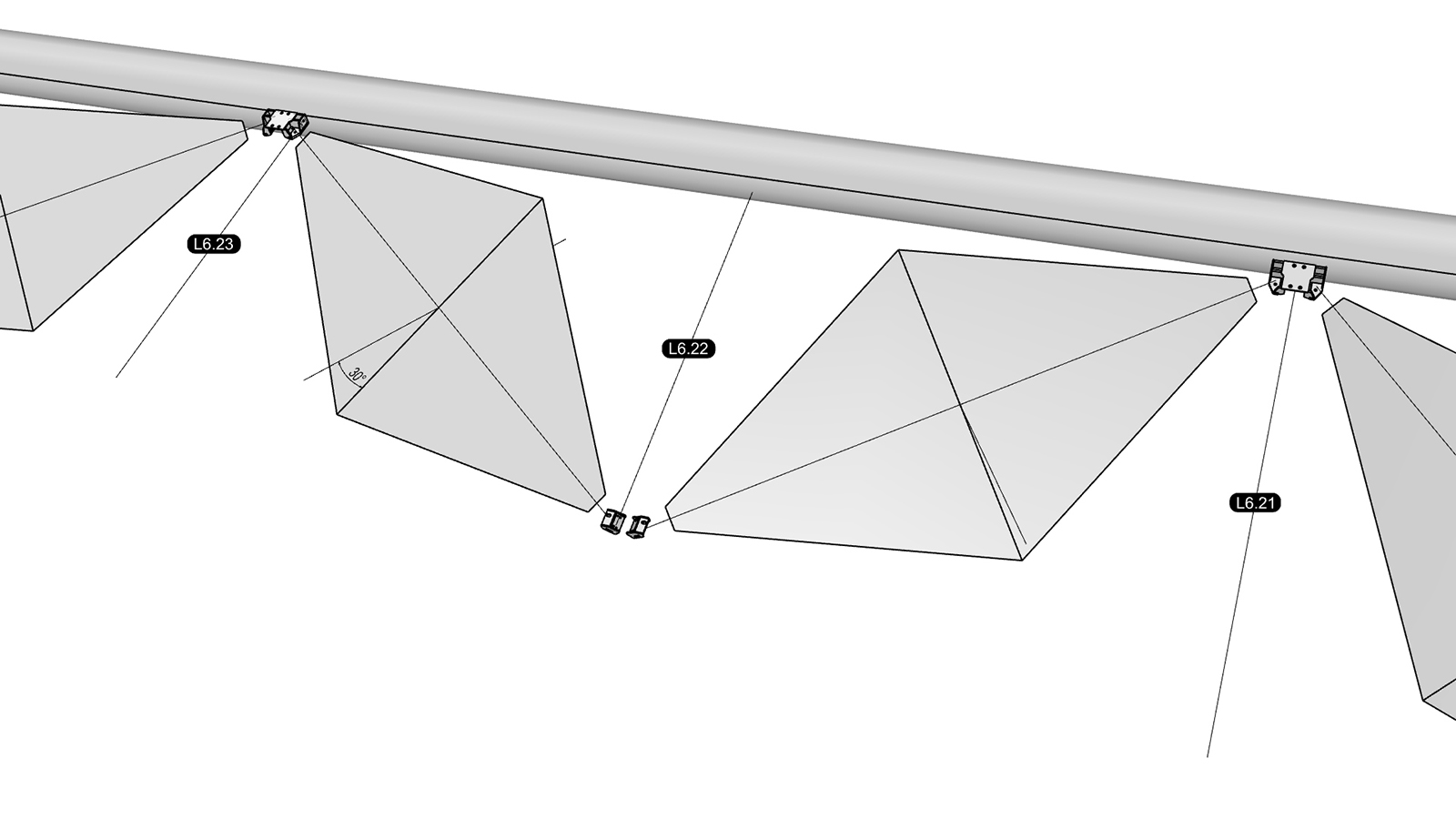
Geometric set-out
The architect’s concept for the sun shading system is geometrically derived in Grasshopper via a set of rules known as ‘parameters’. That is, the model is generated automatically via internal logic arguments rather than through manual manipulation. This process is known as ‘Parametric Design’.


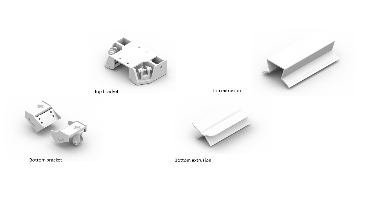
Fixtures
In parallel with the Grasshopper script development, the individual fixtures were being designed by TILT and engineered by Partridge. Although the manufacturing of components is physically one of the later phases of a project, as a process, it was taken into consideration very early in the design process. UTS Central consisted of more than 30 individual components and included items such as aluminium cladding and coatings, motors, gearboxes, driveshafts, bearings, bolts, and so forth.

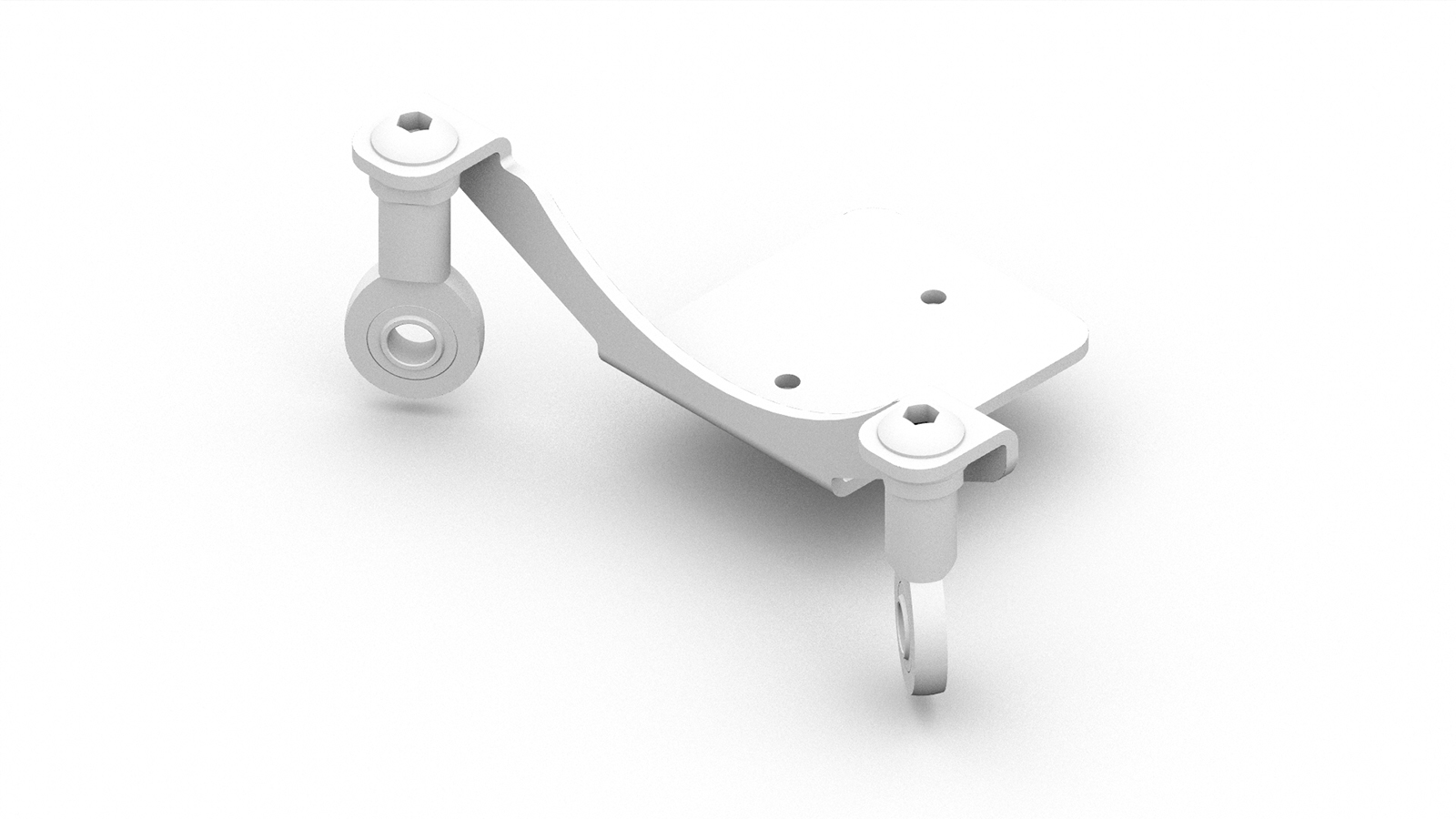
One part which went through substantial design development was the bottom bracket. As the engineering requirements became more evident through the project, the bottom bracket evolved to accommodate these needs.
Bottom bracket evolution – Iteration 1 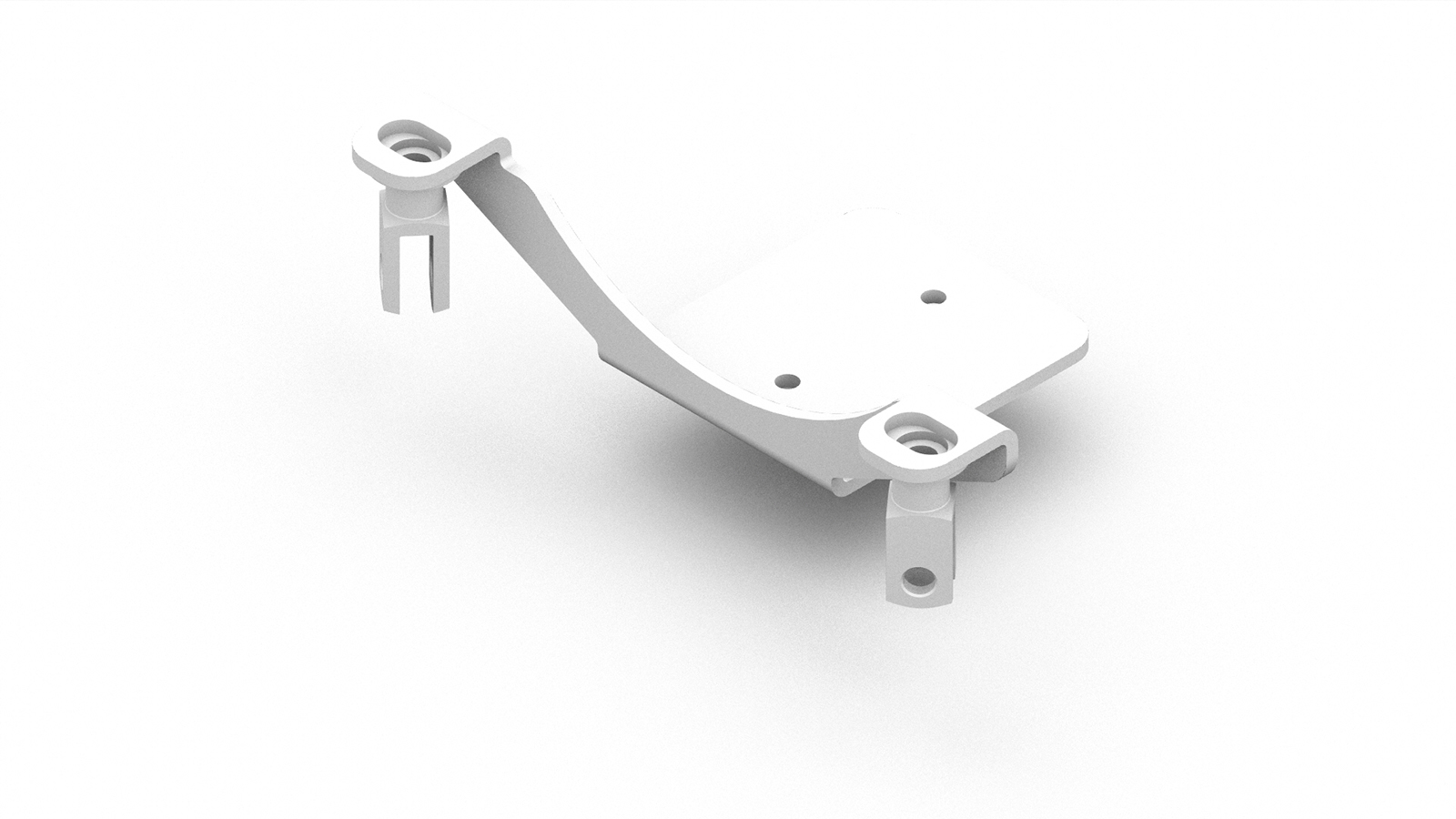
Bottom bracket evolution – Iteration 2 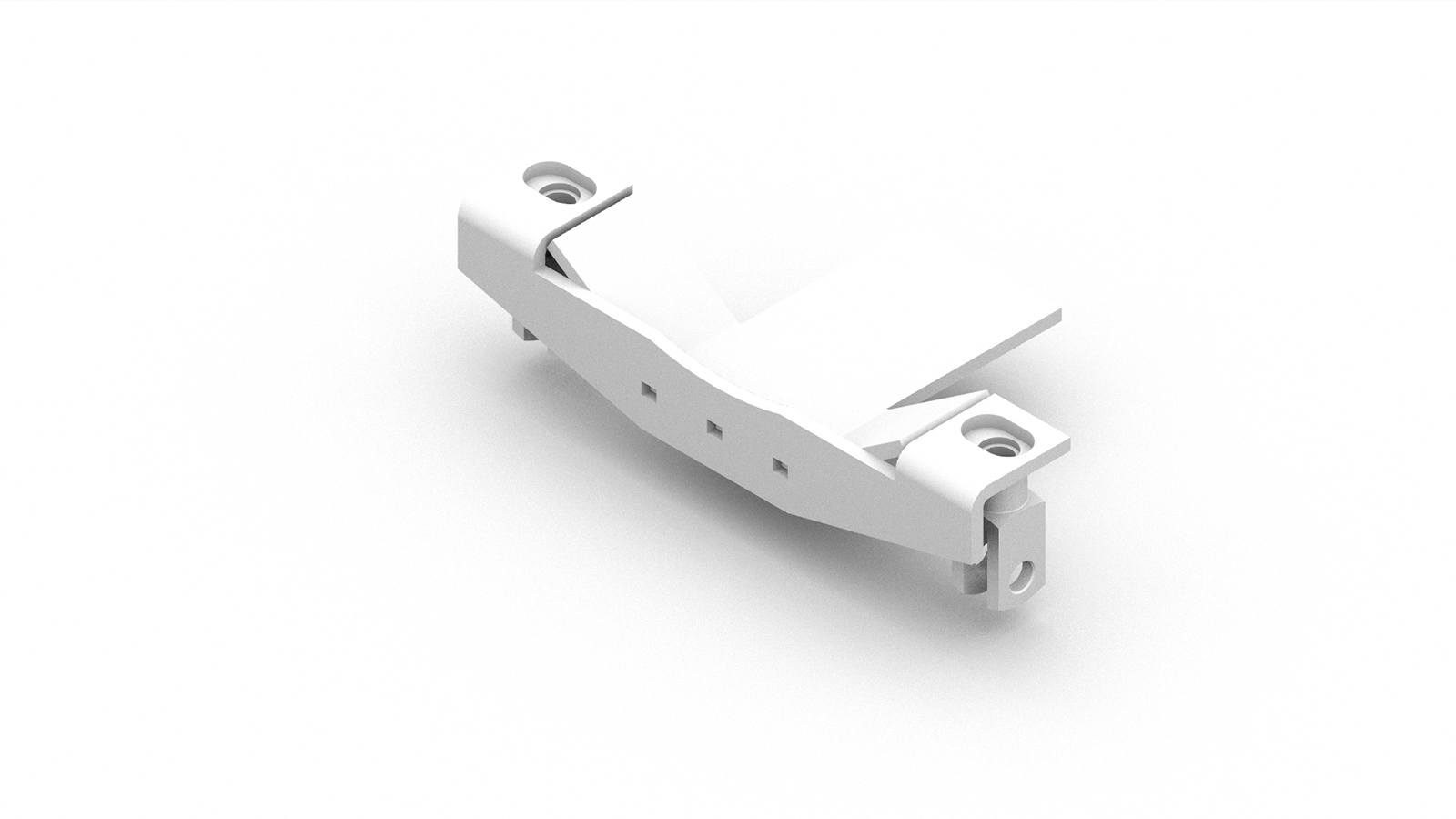
Bottom bracket evolution – Iteration 3 
Bottom bracket evolution – Iteration 4 
Bottom bracket evolution – Iteration 5 
Bottom bracket evolution – Iteration 6 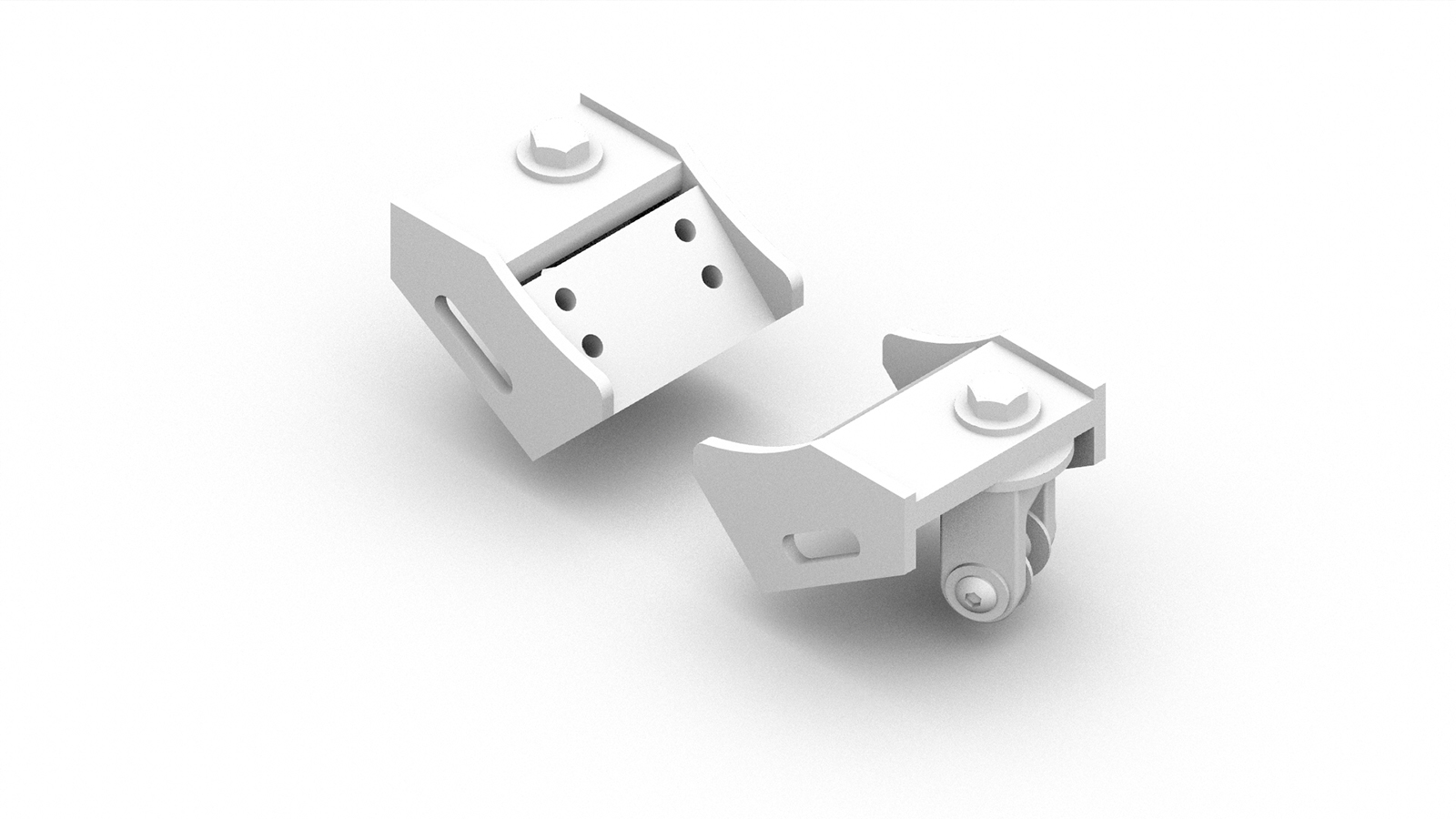
Bottom bracket evolution – Iteration 7 
Bottom bracket evolution – Iteration 8
Understanding that design is an iterative process, workflows were established, which allowed the bottom bracket design to evolve without negatively affecting the parametric model, which was being developed in tandem. For example, since the geometric set-out of the louvres was based on the centre point of the clevis, a set-out point was embedded into each bottom bracket. This point was then referenced into the Grasshopper script, minimising the dependency of the actual geometry of the bottom bracket. This process allowed both the fixtures and parametric model to be developed in tandem.

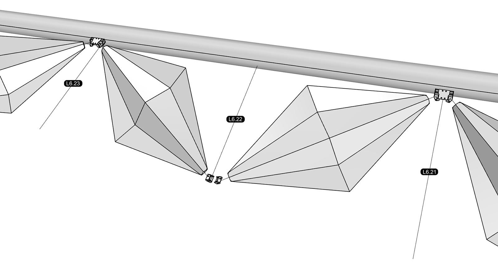
Design development
Throughout the design development process, the Grasshopper script was optimised through best-practice guidelines. This included the creation of clusters to reduce duplicate code. Despite being more efficient, the script experienced a factor of ten development from the initial concept model (LOD 200).
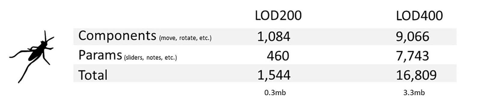
This step-change between a concept-level model and a fabrication-level model can be seen clearly in the images below. The process of adding material thickness, shadow gaps and 1:1 fixings, gives the design far greater visual depth and enhances the initial concept.


Material feedback
The understanding of materials as active participants in the design process is central to all craft. Digital fabrication shifts material thinking into the core of the design process.3 This can be seen in some of the early investigations that were undertaken to ensure the file-to-factory workflow could achieve the project outcomes based on the expected manufacturing processes and materials.
Manufacturing specific software, such as Inventor or Solidworks, have in-built functionality to develop sheet metal flat patterns with bend allowances. Rhino and Grasshopper, on the other hand, have no such functionality as the underlying B-rep unfold operation is a simple geometric process from surface geometry. A comparative analysis was undertaken, which compared the 2D cut patterns from both software.
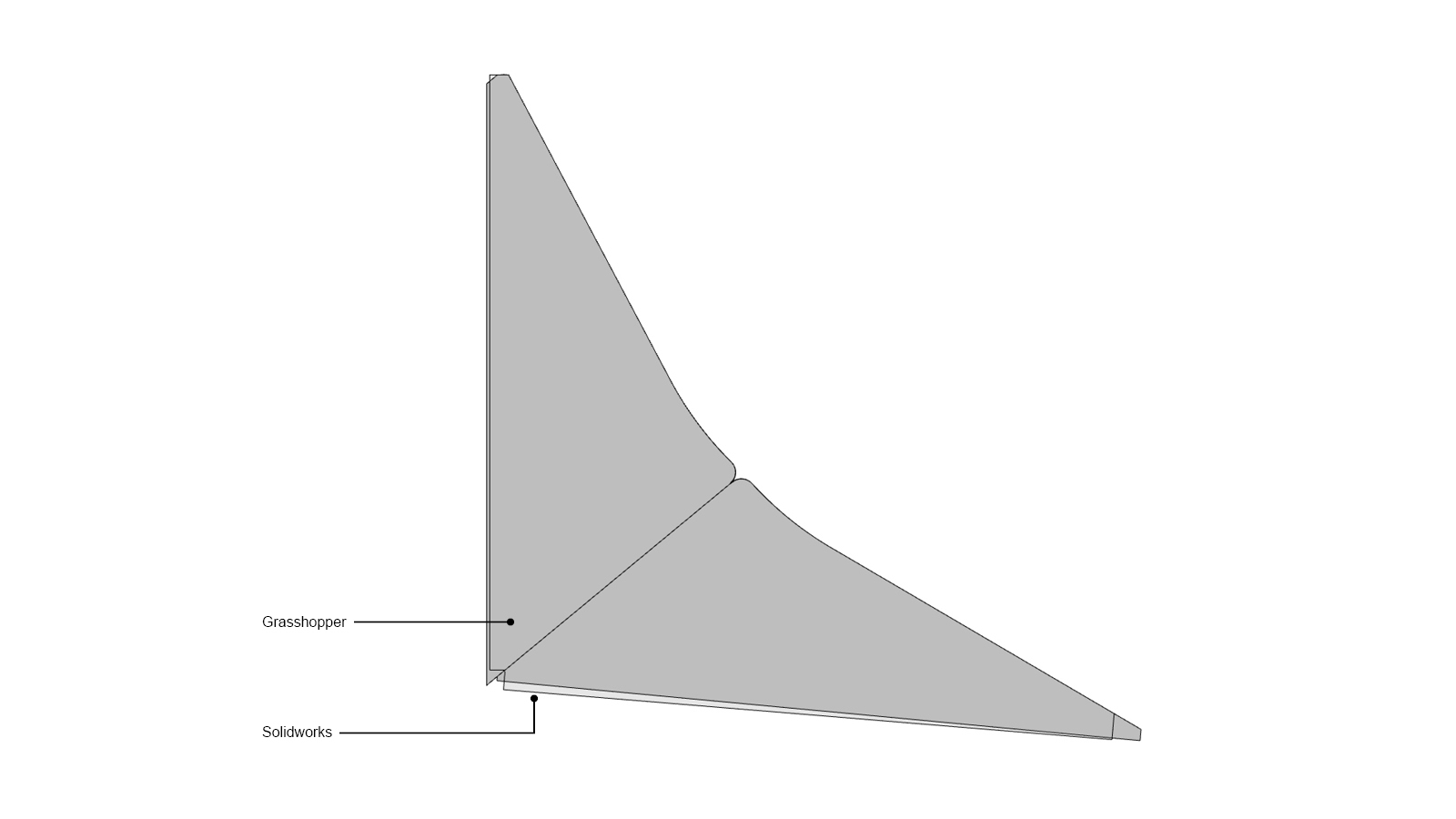
The original design for the cladding required a single piece of metal to be folded multiple times in both directions. This exacerbated the discrepancy between the two cut patterns. Ultimately, however, as the design evolved, the number of folds per panel were reduced. While there were discrepancies between the two results, it was decided that any material elasticity compensation was minimal and could be absorbed through sufficient fabrication tolerances. Consequently, the automation and generative capabilities afforded by Grasshopper provided more significant value to the design process than the need for accurate material elasticity calculation.
Material limits
Another fabrication constraint was the maximum bend angle of aluminium. Beyond a certain threshold, the outer surface of the fold fractures. Grasshopper was able to quickly evaluate all the fold angles in the project and compare it against the maximum fold angle allowed for that particular grade of aluminium. Where the fold angle exceeded the maximum, the input parameters were tweaked until all folds were compliant. Grasshopper, therefore, allowed material-specific constrains to drive the design.
Scan data
The project methodology, timeframe and design geometry demanded that all the sun shading panels be manufactured offsite to fit the supporting steelwork, with limited opportunity for on-site modification. The steelwork was installed by multiple contractors to nominal tolerances. As such, a 3D scan was arranged to determine the as-built structural steel geometry. The scan was conducted by WYSIWYG from below using a tripod-based laser scanner with 0.2mm resolution. The resulting meshes were stitched together and processed with best-fit geometry. This process determined the real-world positions of the set-out points, which were driving the grasshopper script.
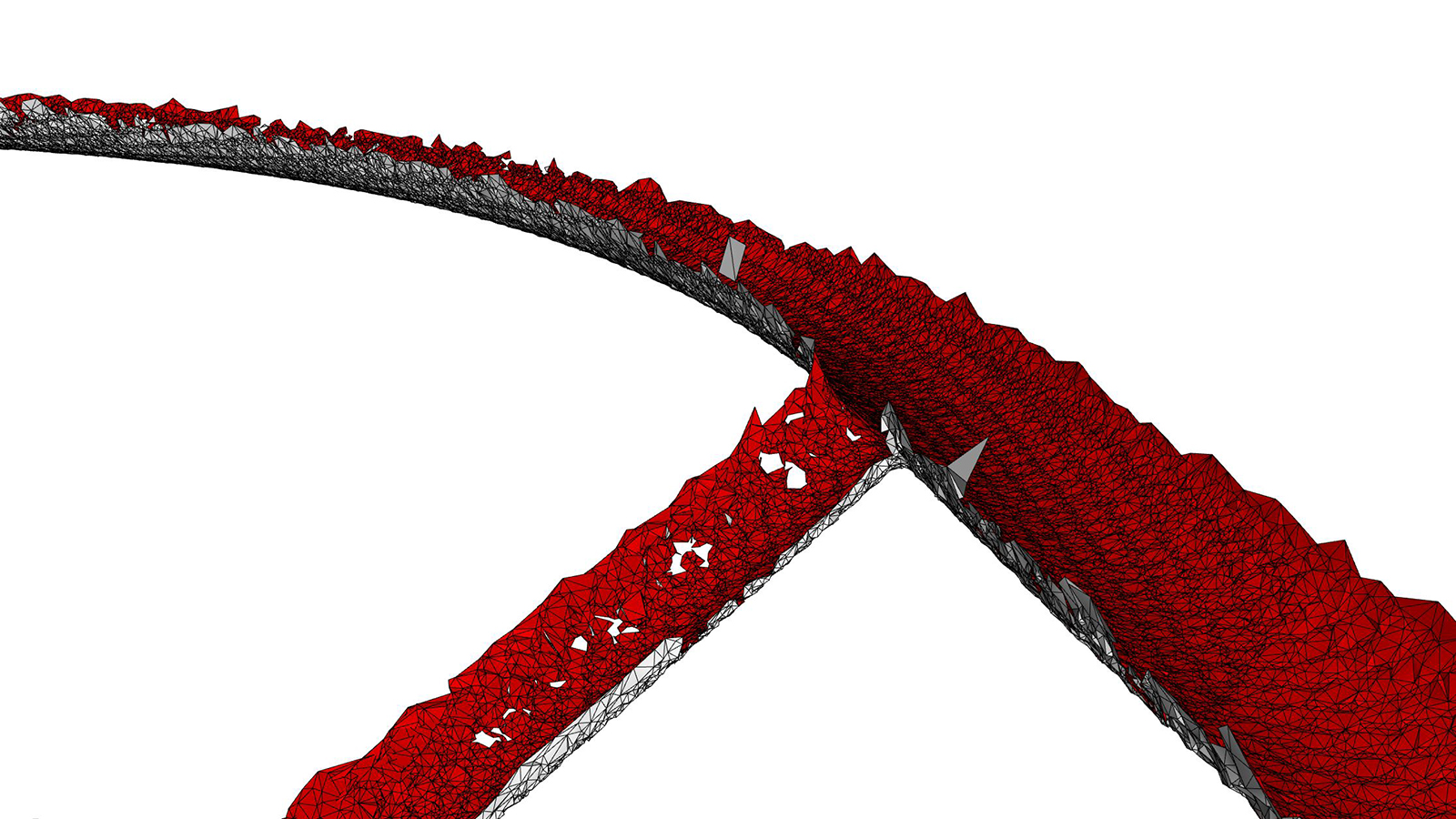
This process unearthed significant discrepancies between the main construction documentation and the as-built elements. While the original Grasshopper script was based on the ‘theoretical’ set-out, the scanned model reported the real site condition.

This variation was accommodated for in the Grasshopper script via a simple Boolean toggle. The toggle enabled the same geometric definition to be run on either set-out condition: Theoretical set-out for BIM coordination; and, scan data for digital fabrication. This allowed two design models to be maintained without any additional computational overhead.
2D Documentation
The parametric design process significantly reduced the time required to document the 108 unique bays. In principle, the 3D model is automatically unfolded to generate 2D shop drawings, with all the associated dimensions and annotations. Of interest in this approach was the benefit 2D drawings bought to the Quality Assurance (QA) process. Over recent years, there has been a strong movement away from traditional 2D drawing deliverables towards a pure BIM deliverable. The argument put forward is that the BIM model contains (or at least should contain) all the required information, including the drawings. While this project was coordinated and reviewed in 3D, the 2D documentation proved invaluable for QA checks. Since all the bays are derived from the same geometric rules, once superimposed, it became easy to identify any bugs in the Grasshopper script.
Clash detection
Since the sun shading system was one of the last elements to be installed on-site, it meant that there was minimal clash detection required. The sun shading system simply had to be designed around the existing elements. A simple Boolean intersection check was run across all the major elements and export to an Excel spreadsheet. Conditional formatting was set up so that clashes could be readily identified in tabular format. This proved far more efficient and effective than navigating the model and undertaking a visual inspection.

BIM deliverable
As part of the client’s BIM deliverable, an IFC2x3 model was required to be submitted. The intention right from the beginning of the project was that this would be generated directly from the Grasshopper model, avoiding any re-modelling or interoperability issues. GeometryGym was consequently chosen as the preferred method to generate the IFC model.
GeometryGym
In general, GeometryGym allows IFC models to be authored via two distinct workflows within Grasshopper. The first method entails creating the IFC element procedurally as you would any element within Grasshopper. For example, generating a sweep path and then defining the profile. This method provides the greatest control. However, due to the complexity of the script and the limited timeframe, this option wasn’t pursued.
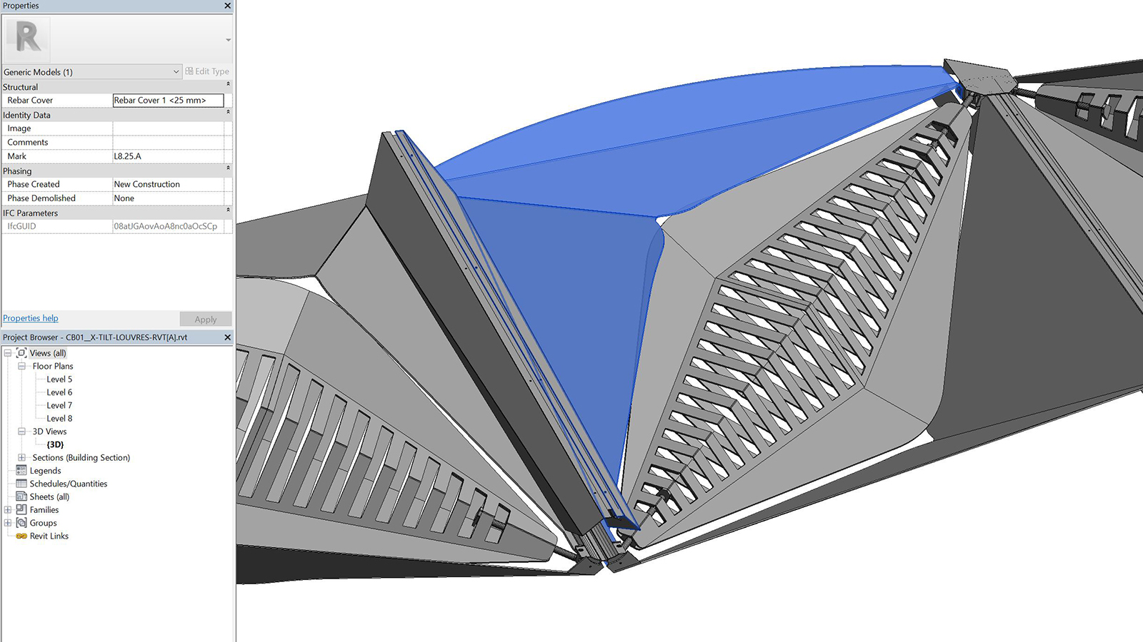
The second method entails using the GeometryGym components to reference in baked Rhino geometry and then reverse engineer the geometric process. This meant that complex geometry could be simply referenced into Grasshopper from Rhino. GeometryGym would then determine if it was an extrusion, or B-rep, etc. and then create the associated IFC model. This proved to be an incredibly efficient way of generating an IFC model. The resulting geometry was clean and free of unnecessary surface triangulations while still maintaining all of the embedded data, such as ‘Mark’ values. The IFC model was able to be imported directly into Revit using GeometryGym’s IFC import tools.
Manufacturing
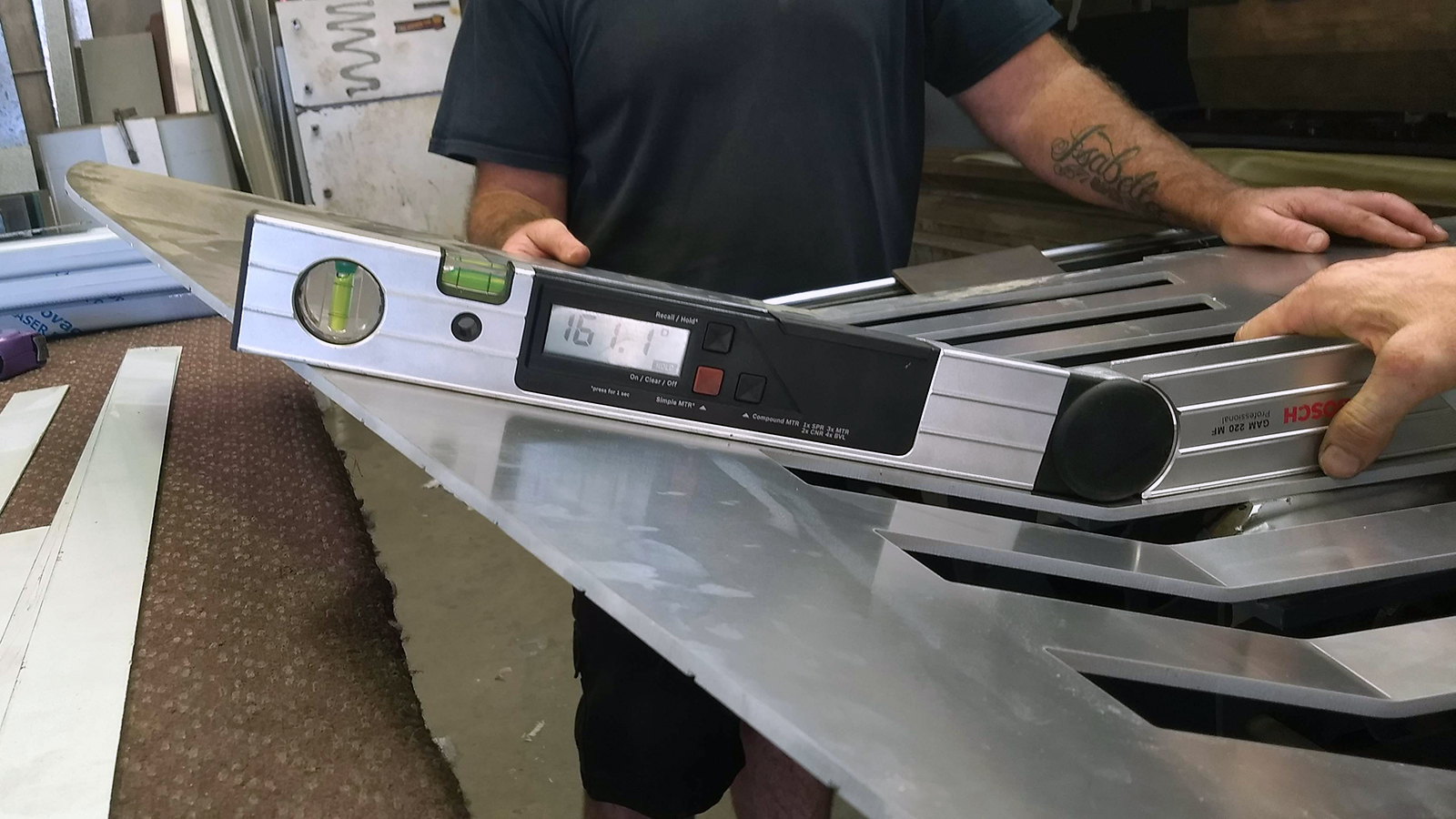
Fabrication of the main louvre and cladding panels were undertaken by Architectural Metalwork Australia (AMA). While it was possible to generate nesting patterns within Rhino with the aid of plug-ins such as RhinoNest, AMA used their nesting software for connection to the CNC machinery for cutting.

Due to the irregular shapes and non-standardisation of the panels, each panel was manually aligned along the fold line. The panels were then CNC folded to within 0.1 degree of accuracy. The supplied check dimensions were used to verify that the overall panel dimensions met specification. While some of this process was labour intensive, it is important to note that alternative technologies exist which are capable of even greater automation. RoboFold for examples uses multiple industrial robots to fold sheet metal.4
Installation
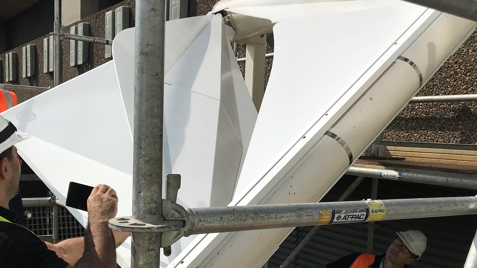
Unlike traditional construction, prefabrication allowed the team to complete much of the assembly in the workshop prior to site. This allowed the on-site installation to be quick and efficient and removed much of the risk that can arise on site. A significant component of the installation process was the commissioning of the operable louvres. This was the first time the client and design team could see the results of the enormous effort that went into the design and production of them.
Conclusion
The convergence of CNC machines and digital design tools offer unprecedented freedom for the fabrication of geometrically complex parts and non-standard design solutions. Taken as a whole, digital fabrication puts the power of making in the hands of the design professional. As Randy Deutsch describes, ‘the historical separation for design and construction means and methods – for liability, legal, and insurance reasons – is starting to blur, and the industry is moving closer to a unified workflow.’5

The UTS Central project is an exemplar of how an architect’s design intent can be maintained through the use of material-specific design solutions, parametric modelling and digital fabrication. Moreover, it demonstrates how to move beyond BIM and simple geometric representation into a digitally fabricated world.
If you are interested in finding out more about how Parametric Monkey can help your project, please contact us via our website.
References
1 Agarwal, R. et al. (June 2016). Imagining construction’s digital future. McKinsey & Company.
2 Day, M. (20 May 2019). Embracing digital fabrication. In AEC Magazine.
3 Ramsgard, M. & Tamke, M. (2013). Digital crafting: Performance thinking for material design. In AD Inside Smartgeometry: Expanding the architectural possibilities of computational design. Peters, B. & Peters, T. (eds). John Wiley & Sons, Chichester, p.243.
4 Epps, G. (May/June 2014). RoboFold and Robots.IO. In AD Made by robots. John Wiley & Sons, London, pp.68-69.
5 Deutsch, R. (2017). Design and fabrication. In AD Convergence: The redesign of design. John Wiley & Sons, Chichester, p.167.


6 Comments
Kai ZhuKai
Great work and informative post!
Structurals
What are the advantages and limitations of using digital fabrication techniques and How does digital fabrication impact sustainability and environmental considerations in manufacturing?
Paul Wintour
The advantage of digital fabrication is you are going direct from file-to-factory. There is no re-handling of drawings or data. The limitation is that the model needs to be 100% accurate. What gets modelled gets fabricated.
Digital fabrication, I don’t think really impacts sustainability. The same elements are getting fabricated; it is just being done in a more efficient manner.
giusseppe lund
Thanks for this informative description Paul….as a user of rhino and grasshopper for many years I am trying to utilize the extra capabilities of Elefront components but having difficulty finding instructive references and tutorials. I would much appreciate your recommendations
regards Giusseppe
Paul Wintour
Hi Giusseppe. Try this tutorial and see if that helps: https://parametricmonkey.com/2016/04/14/elefront/
Justin Imhoff
Fascinating insight into development of this parametric model and it’s construction. Amazing. I made the animation you linked to. It was an honour to show it off. Thanks for creditting Realfeel.