
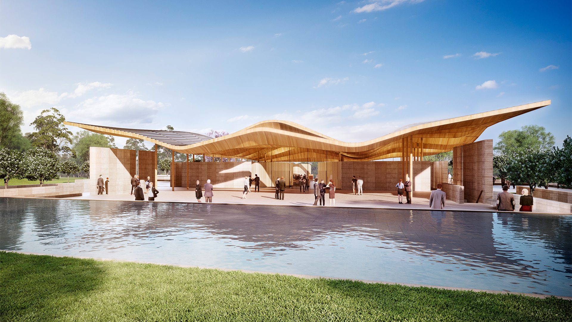
This case study will present the Macarthur Memorial Park as an exemplar of parametric modelling and digital fabrication. Spanning 113 hectares and surrounded by rolling hills and lush greenery, Macarthur Memorial Park is designed for peace and reflection. The project, which opened earlier this year, comprises an admin building, café, chapel, function centre, and gatehouse, with each building featuring a self-similar, ‘floating’ roof. By deriving the soffit geometry via a set of rules, the parametric system adapted to each unique roof form, enabling an efficient and accelerated shop drawing process.
Introduction
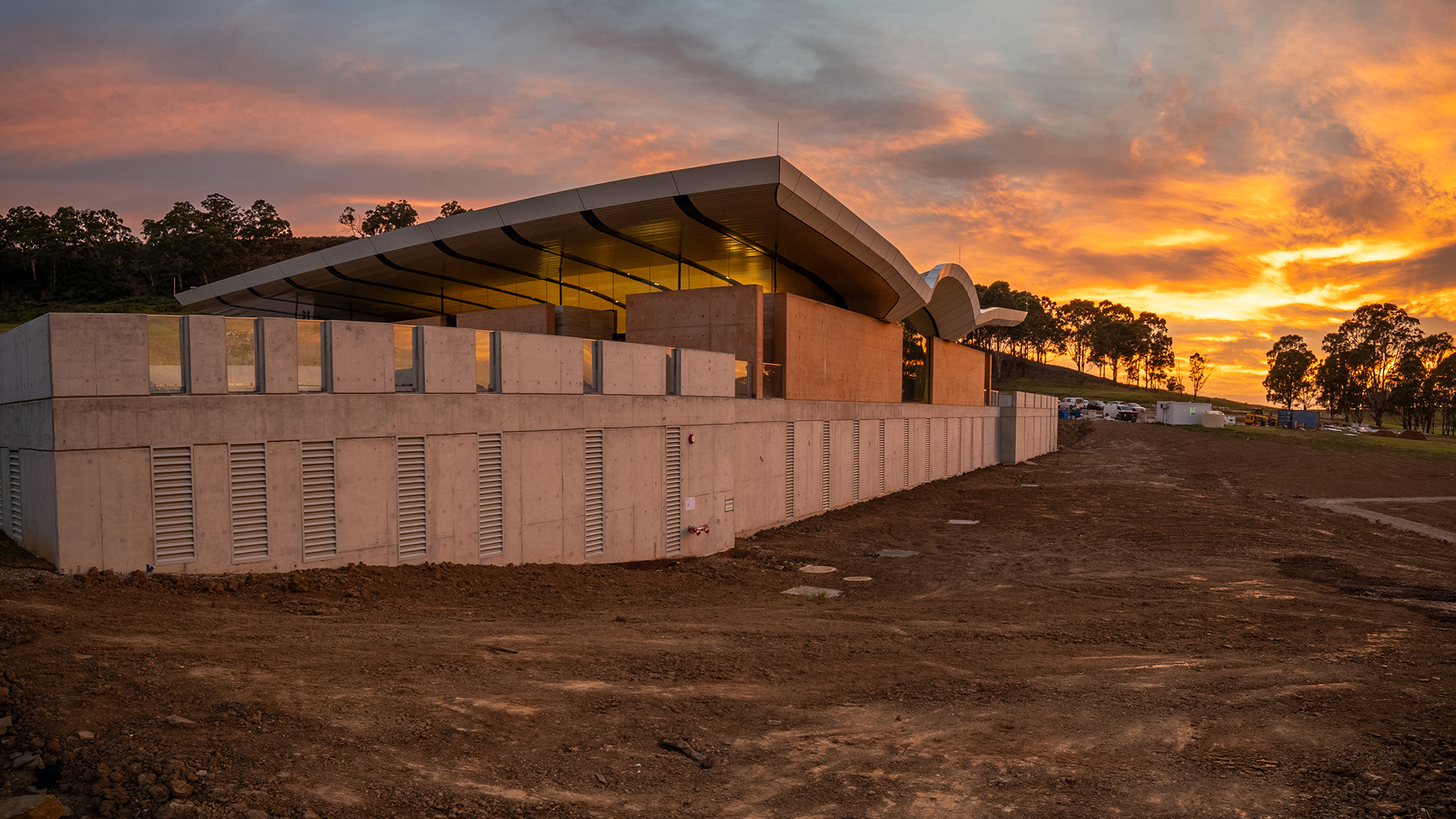
Macarthur Memorial Park is located at Varroville, Sydney and is run by the Catholic Metropolitan Cemeteries Trust. The project has been in development for over a decade, with the original master plan and concept design created by FJC Studio back in 2014. However, obtaining the necessary statutory approvals significantly delayed the project’s start. Eventually, a change in state government in 2023 saw the project regain momentum, with Paytner Dixon awarded the Design and Construct contract. The entire site spans 113 hectares and features an administration building, café, chapel, function centre, and gatehouse, all surrounded by rolling hills and lush greenery.

As part of an Early Contractor Involvement (ECI) process, Savcon was commissioned to support the design development of the chapel soffit. With Parametric Monkey assisting, the ECI process explored geometric rationalisations, buildability and materiality. Parametric Monkey was then further engaged to provide parametric modelling and digital fabrication services (LOD400) for the internal and external soffit for each of the five buildings. The most complex of the buildings was the chapel, known as ‘the Sanctuary’, which this case study will primarily focus on.
Chapel development
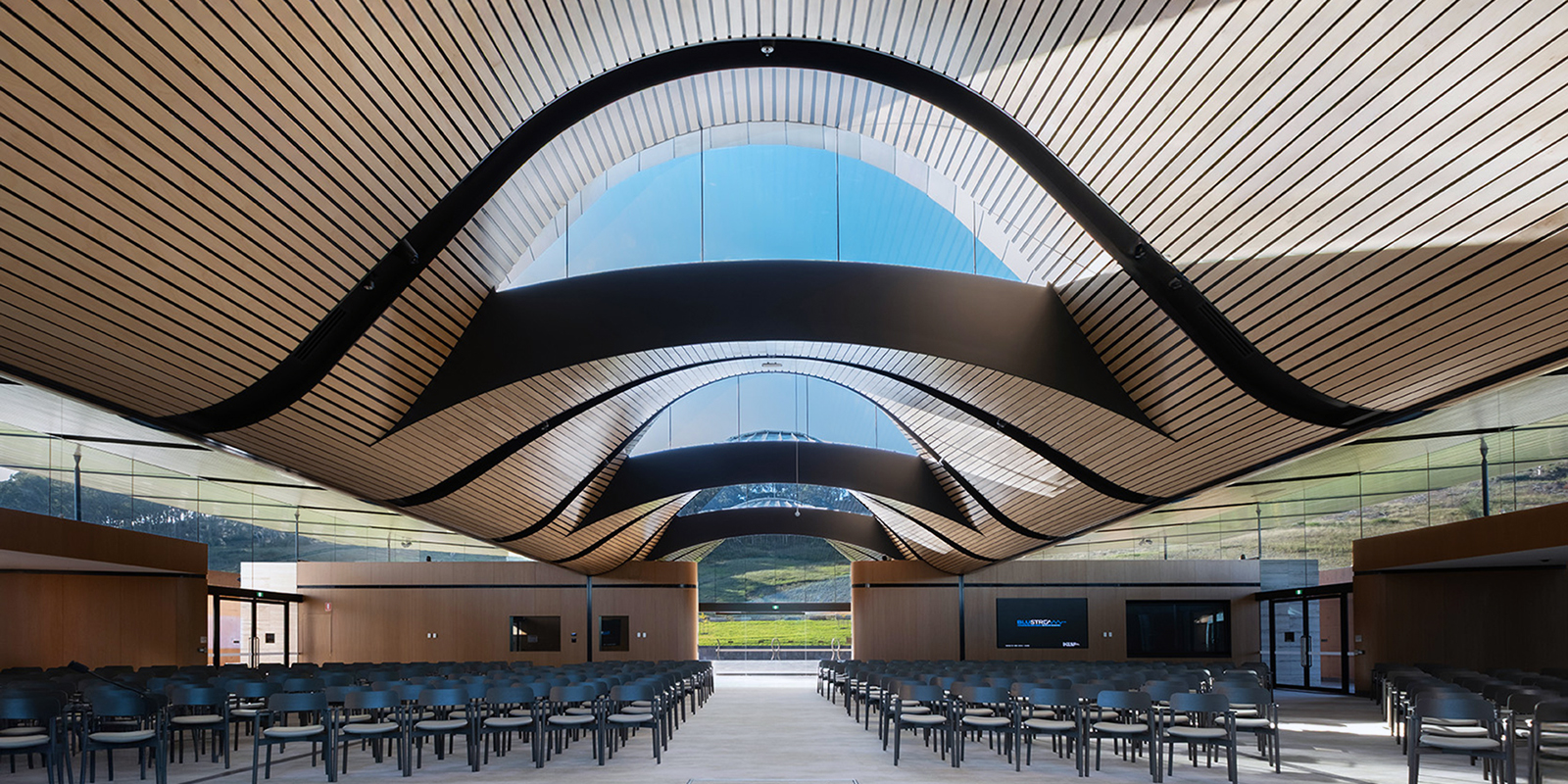
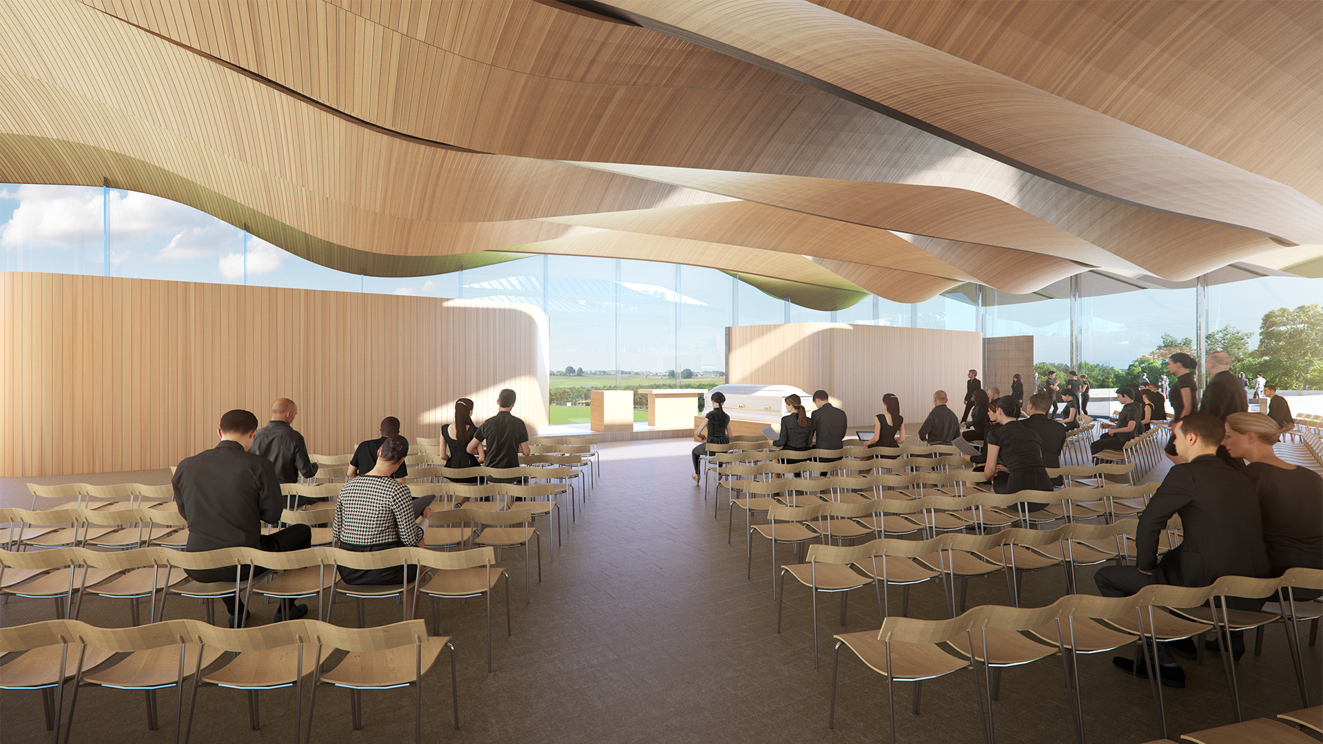
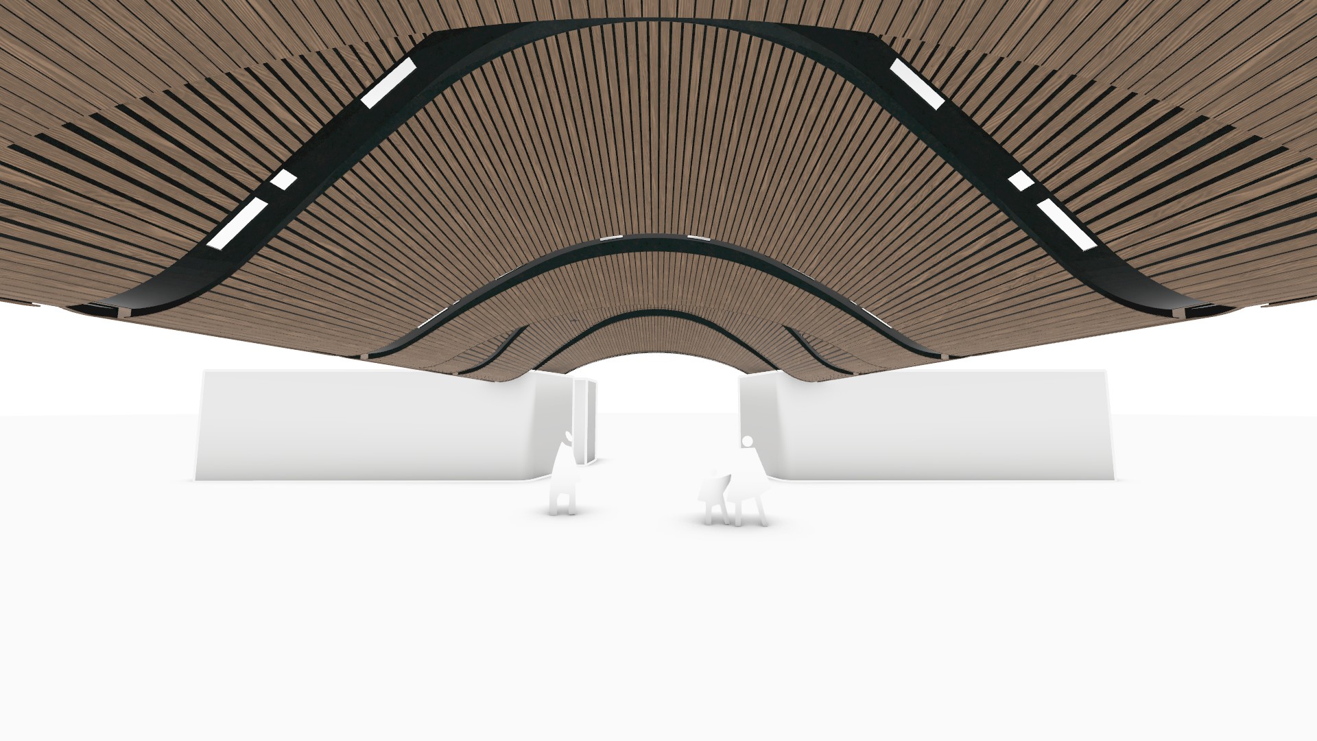
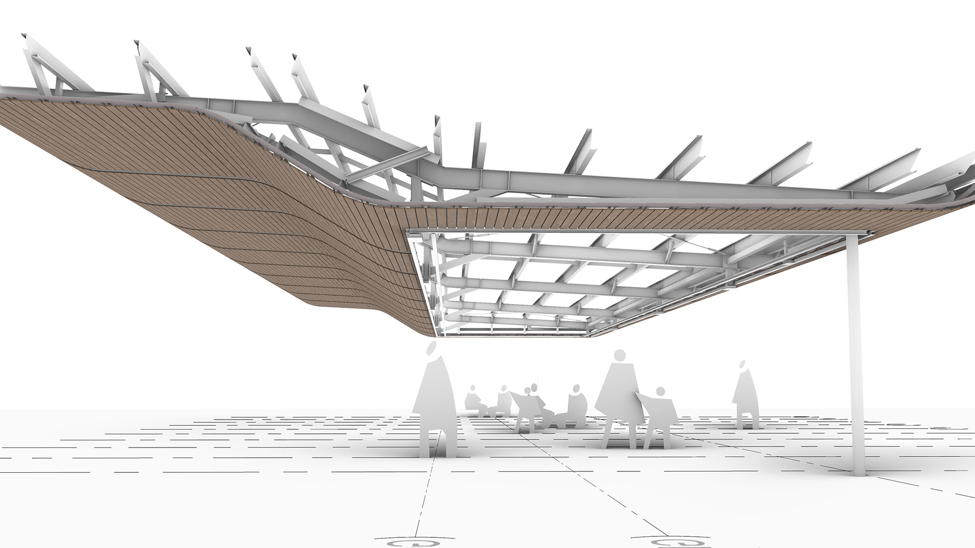
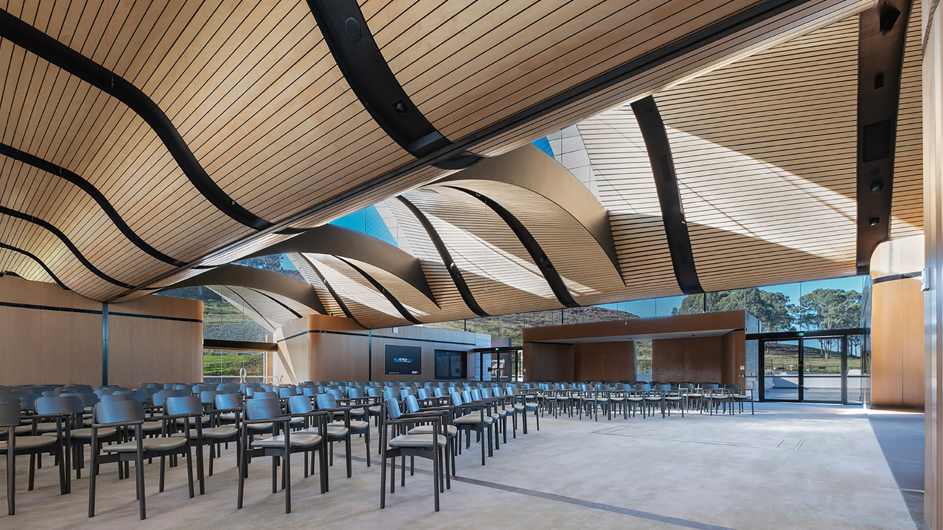
FJC Studio originally conceived the chapel roof as a series of geometric transformations to create an undulating form that expresses the site’s topography. The form was then further manipulated to allow a series of skylights that face north, allowing light to penetrate the front of the chapel. The result was an organic soffit consisting mostly of double curvature.

Due to cost escalations over the duration of the project, much of the double-curvature geometry was rationalised by Paytner Dixon during the value engineering process. Despite this, the revised design maintained the double-curvature vaulted soffit in the centre zone, which required careful geometric precision both digitally and physically. Due to this requirement, Grasshopper and Rhino were adopted for their advanced fabrication capabilities.
Geometric set out
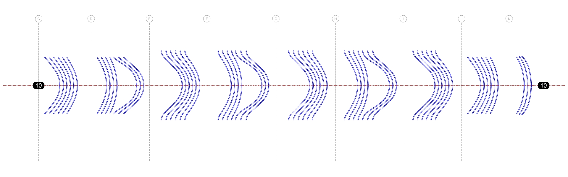
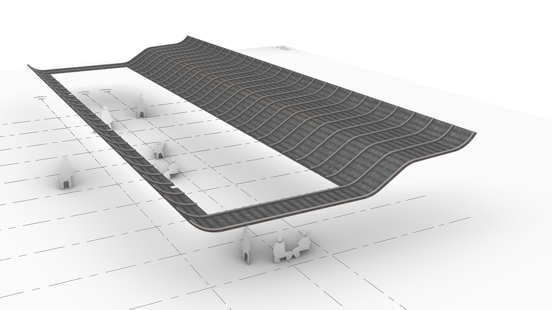
Defining the key setting-out points is crucial for any project, particularly when dealing with complex geometry. In our experience, defining these points in diagrammatic form is highly beneficial as it makes the naming convention and underlying geometric logic driving the geometry explicit. It also highlights any areas that could benefit from rationalisation. The ‘finished face’ of the soffit was chosen as the main set out, and this curve drove the overall parametric system, which was applied to all buildings.


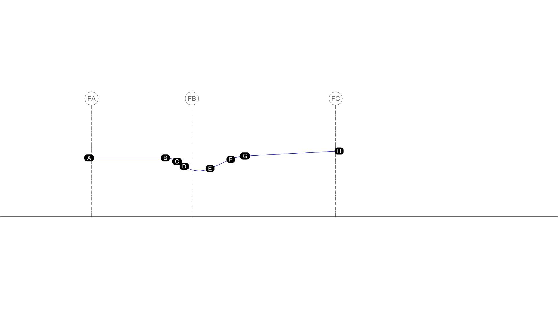

Once the section profile was established, the next step in the parametric workflow was to generate the slat geometry. However, the chapel soffit had a mix of both single and double curvature base surfaces. The North and South zones formed the ‘wings’ of the chapel and were single curvature only. Conversely, the central zone, which consisted of the vaulted skylights, was double-curvature. Therefore, different solutions were required that took into consideration the underlying geometry, materiality of the elements and overall buildability.
Slat geometry
North & South zones
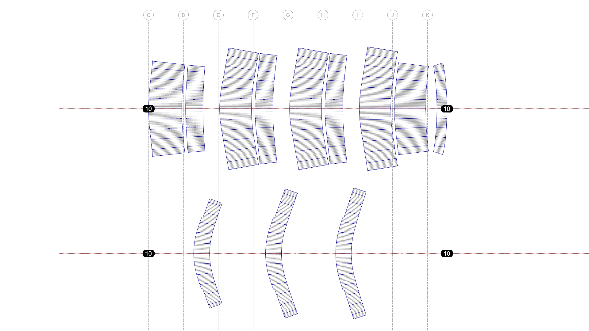
For the north and south interior zones, the ‘slats’ were actually 1200x13mm MDF panels with shiplap joints and routing to mimic individual slats. The main benefit of the panelised approach was prefabrication and quicker installation. The parametric model first generated the panel’s profile in its planar state, before deforming it to conform to the base surface, therefore mimicking the physical installation process. Once deformed, the panel profiles were simply extruded in the digital model, and the various penetrations and cutouts removed.
The panels were then digitally ‘unrolled’ into their planar form for digital fabrication. However, for the physical panel to conform to the soffit curvature, a series of relief cuts was needed on the back face of the panel. Known as kerfing, the technique is more art than science, and the Savcon team undertook a series of prototypes to experiment with the spacing and depth of cuts, ensuring the desired curvature could be achieved without breaking the panel.
Central zone
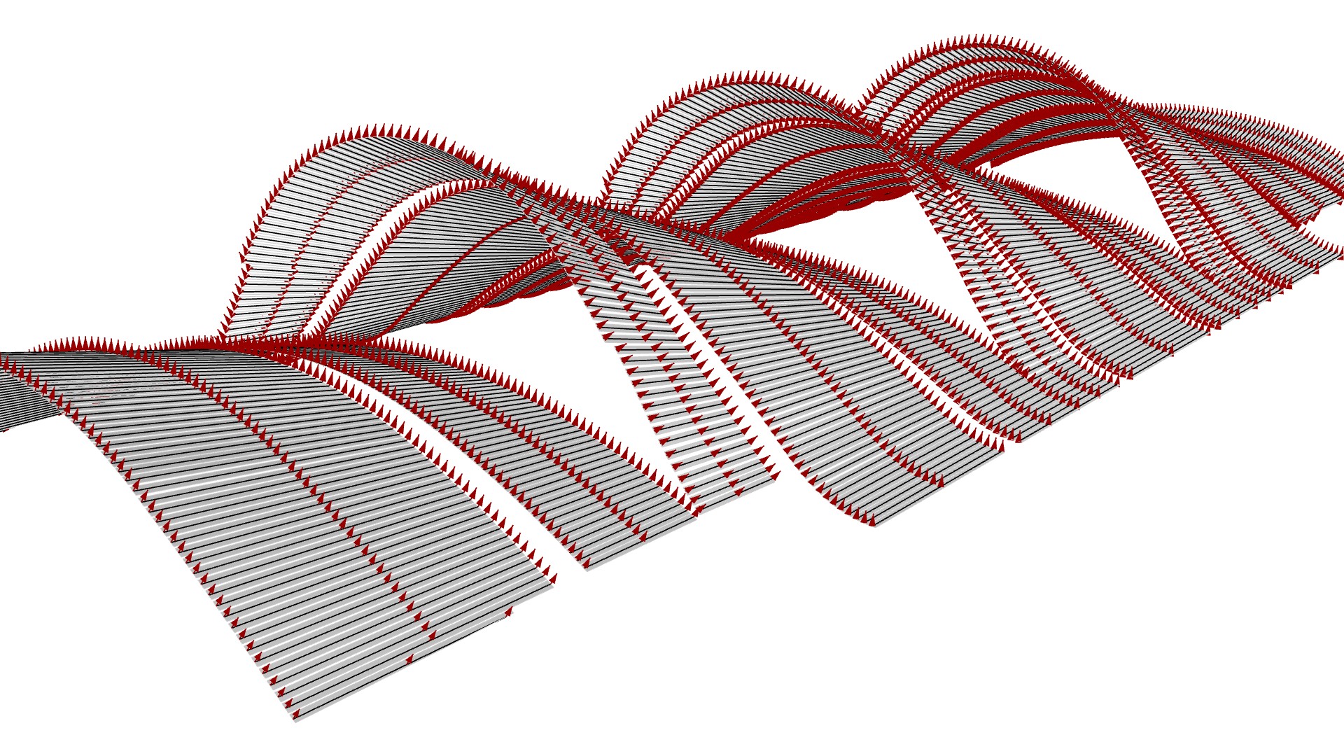
For the interior central zone, 88x6mm individual timber slats were chosen over a panelised system, as they could be twisted to conform to the soffit’s double-curved base surface. To generate the slat geometry, the parametric model first needed the slat centrelines. However, unlike the north and south zones, the slats in the centre zone needed to taper to ensure consistent spacing. This tapering is a direct result of having two profile curves of varying lengths needing to be divided equally.

Next, the slat geometry needed to be calculated by giving the centreline geometry width and depth. However, as the base surface had double curvature, the normal along the slat centreline varied. In other words, the base surface was not planar; it was warped. This warping was necessary to make the slats appear visually continuous end-on-end. Additionally, the warping needed to be shown for coordination and shop drawing approval, as ultimately, this is how the slays would be installed.
However, for fabrication, the slats needed to be planar. Only during installation would they be twisted. These conflicting requirements highlight the discrepancies that can occur between the digital and physical worlds, and resolving them can be deceptively complex, as it often requires parallel workflows to satisfy the two requirements.
Exterior
Due to concerns with durability, the external slats were made of aluminium. However, to enable prefabrication and speed up the installation process, slats were grouped and connected with flexible aluminium straps. This method also ensured the slats could be accurately positioned to maintain visual continuity between the interior and exterior.

Service recess
With the slat geometry defined, the next step in the parametric model was to generate the service troughs, which concealed the lights, audio-visual equipment, fire sprinklers and smoke detectors. To ensure a clean finish, all of the penetrations in the service zone needed to be pre-cut. However, since the 2D reflected ceiling plan was diagrammatic only, the penetration shown in plan didn’t account for the curvature of the recess. To resolve this issue in the digital model, 2D points were placed on the ground plane at each fixture’s centre point. The points were then projected onto the soffit base surface, and the ‘normal’ found. Finally, a ‘true’ cutout was created perpendicular to the surface normal.
The service trough surface was then digitally unrolled to create a flattened surface for digital fabrication. Again, relief cuts were added to ensure the panels could conform to the desired curvature.

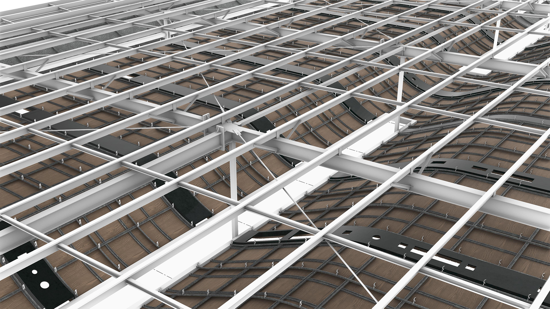
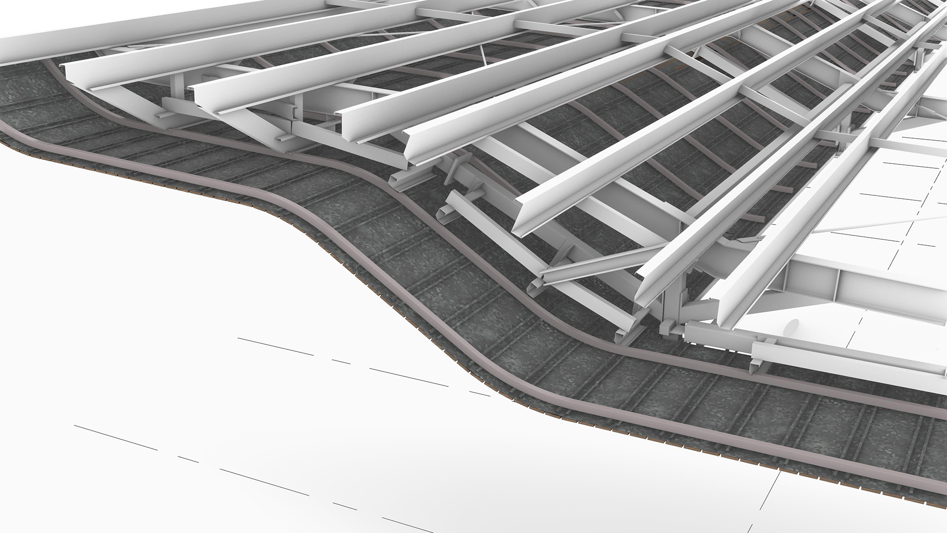
Substructure
One of the misconceptions with complex geometry is that once you have the shape, the rest is easy. In fact, it is the total opposite; the parts that you don’t see are often the hardest. They literally do the heavy lifting. And for this reason, the substructure is the unsung hero of complex geometry.
North & South zones
For the interior north and south zones, standard furring channels with a Top Cross Rail (TCR) and hanger clips were used as the substructure. However, because of the pitch of the soffit, a double layer of furring channels was needed so that the ceiling hangers could be vertical. While most of the elements were linear extrusions, the curved elements needed to be pre-rolled off-site, requiring the digital model to be accurate and precise.
Central zone
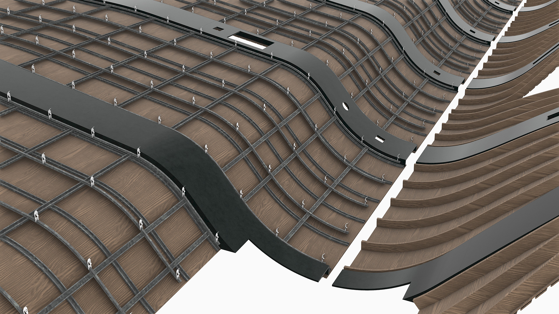
For the interior central zone, standard furring channels wouldn’t have been able to conform to the double curvature base surface. As a result, an alternate and more flexible system was adopted, which comprised of MDF backing panels and vertical ‘ribs’. Due to the double curvature of base geometry, each of the backing panels and ribs were unique and needed to be documented individually.

The vertical ribs were already planar, so no geometric modifications were required for fabrication. As a result, the Grasshopper script simply flattened and arrayed the ribs so that they could be CNC cut.
For the backing panels, these were double curvature and needed to be unrolled into a planar state for digital fabrication. Since it is not possible to accurately unroll a double-curvature surface without deforming it, digital prototypes were undertaken to ensure that any deviation was within tolerance.
Additionally, the backing panels’ joints were concealed behind the slats, allowing for any on-site tolerance issues. Finally, to assist with the installation of the slats, the slat centreline was inscribed into the backing panels. These lines created a visual aid so that slats, which couldn’t be prefabricated off-site, could be easily installed in situ.
Exterior
The exterior substructure zones consisted of Square Hollow Section (SHS) and ‘Top Hat’ framing, combined with sheet metal backing located behind the slats for protection against vermin. Again, the curved SHS elements needed to be pre-rolled off-site, requiring the digital model to be accurate and precise.

A computational design approach
The overall project comprised five buildings: an admin building, a café, a chapel, a function centre, and a gatehouse. Since each soffit form was unique, manually modelling each building would have been a time-consuming and expensive process. However, because each soffit was self-similar, it enabled the geometry to be parametrically derived via a set of rules. This parametric system could then be applied to each building, with only minor modifications. The result was an accelerated documentation process that automatically adapted to the evolving design, whilst establishing a file-to-factory fabrication workflow. With extensive use of prefabrication, parts simply slotted into place, allowing the team to achieve the aggressive program deadlines.


Conclusion
Construction of the project was completed in January 2025, with the official opening in April. Overall, the project showcases how digital fabrication can be used to close the gap between digital technologies and the physical construction process. The file-to-factory workflow enabled faster construction process, minimised resources, and allowed material-specific design solutions.


If you are interested in finding out more about how Parametric Monkey can help your project, please contact us via our website.