

When teaching an introductory Revit class, I’m often asked ‘where do I begin?’. He is a step by step workflow to help newbies get up and running. Refer also to this tutorial for best practice tips.
Step 1 (Optional): If tracing a design, vectorise drawings
- To import a raster image in AutoCAD, type ‘XR’ to bring up the External Reference window and select Attach image (*jpg). Scale the image as required and trace.
- To import a raster image in Rhino, go View > Background Bitmap > Place (*jpg). Scale the image as required and trace. Save the file as a *dwg for import into Revit.
- If the file is a *pdf, you can open the file directly in Rhino. Save the file as a *dwg for import into Revit.
Step 2: Clean up the CAD drawings before importing
- Delete anything unnecessary, e.g. hatches. The simpler, the better;
- Flatten;
- Purge unused;
- Audit; and
- Reposition to 0,0,0 if necessary.
Step 3: Link *dwg plan into Revit
- Visibility Graphics (VV) > Model Categories > Site > Project Base Point, and check the box. This element is Revit’s internal 0,0,0 point. It is best-practice also to use this as your 0,0,0 point as if you move it too far away you will get rounding errors. To find out more about this topic, refer to this tutorial
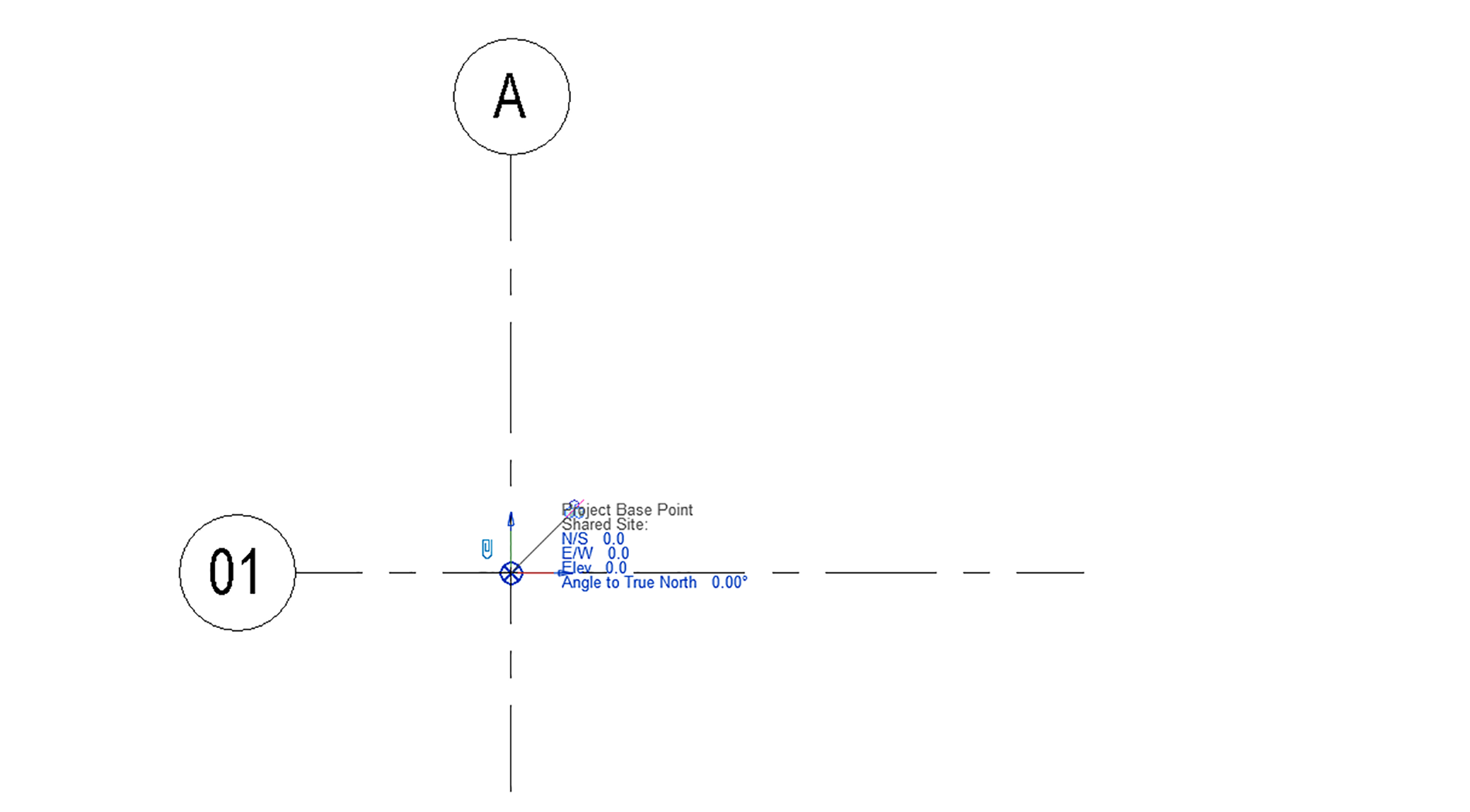
- Link CAD plans. Insert > Link CAD (*dwg). Click to place the drawing anywhere and move so that the intersection of your grid (A1) aligns with the Project Base Point. Ensure that you ‘Link’, not ‘Import’.

- Note that if your *dwg contains both plans and sections/elevations, you are best to separate these into separate files as you will not be able to import the same link into both a floor plan and section.
- Pin the base plan. Select the CAD plan > Modify > Modify > Pin (PN). This check will prevent the plan from accidentally moving.
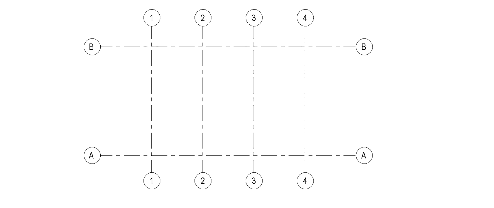
Step 4: Setup grids
- Architecture > Datum > Grid. Draw or copy as required.
- Pin grids to prevent them from accidentally moving. Select all the grids > Modify > Modify > Pin (PN).
Step 5: Setup levels
- Create section to see level by going View > Create > Section. Draw the section mark. Right-click on the section mark and select ‘Go to view’.

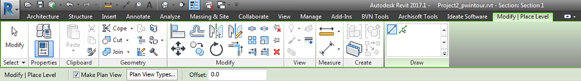
- Create levels. In the section view, drag the level markers to the correct height as required. To add additional levels, Modify > Modify > Copy (CO) to copy up, or Architecture > Datum > Level to create new ones. Note that levels are 3D elements and that depending on where you create your section, you may or may not be able to see the levels.

- Ensure that you have the ‘Make Plan View’ enabled when creating levels as it is possible to create levels without an associated floor plan. If you accidentally forget this, go View > Create > Plan Views > Floor Plans and select the levels for which you want new views
Step 6: Setup sheet list
- This list will be your deliverables. To create a new sheet, go View > Sheet Composition > Sheet. Alternatively, you can go to the Project Browser, and right-click on Sheets and select New Sheet.

- Drag and drop views onto the sheets. Remember that a view can only exist on one sheet. If you want to show it twice, you’ll need to duplicate the view and assign each to a separate sheet.
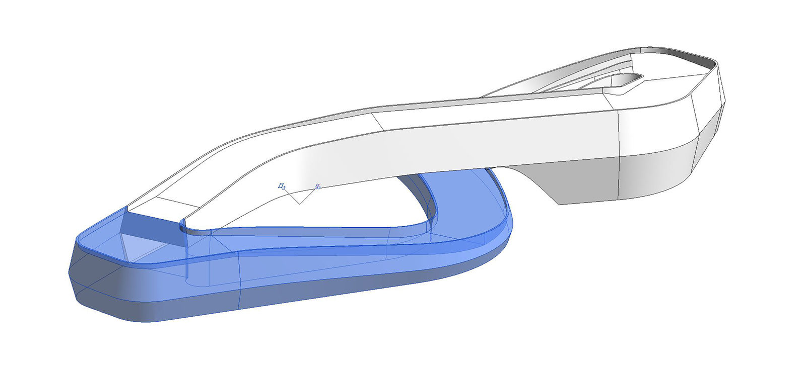
Step 7: Conceptual modelling in Rhino/SketchUp/Maya/etc (if required)
- Revit has a limited ability to deal with complex forms. If you need to incorporate this step, refer to this tutorial for more information.
Step 8: Commence detail modelling in Revit
- Architecture > Wall: Architectural. Set the location as required (usually ‘wall centreline’ or ‘finished face exterior’). Under Draw, select ‘pick lines’. Pick the AutoCAD lines to recreate as walls within Revit.
Like anything, the trick is to start basic and gradually increase the level of detail. Best-practice is to model how you would build it. Happy Revit-ing!


