
Managing wall types within an architectural project is a vital Construction Documentation process. Each wall type must be tracked so all parties know the layer build-up and performance requirements, such as fire or acoustic ratings. This tutorial describes how Dynamo can manage this process by automatically renaming wall types.
Wall type naming conventions
Historically, architects have codified their Construction Documentation to increase flexibility, efficiency and consistency. Within Revit, this is achieved through several means, including tags and keynotes. The codes link the drawing and the full description in the specification. For example, ‘CONC-1’ may denote ‘Class 2 concrete finish, acid-etched’. Whereas ‘PB-1′ may denote ’13 mm impact-resistant high-density plasterboard’. To further complicate things, codes are often nested into other codes, so for example, ‘P1’ (Partition Type 1) might be comprised of PB-1 (Plasterboard type 1), INS-1 (insulation type 1), etc.

The problem
The problem with this method is two-fold. Firstly, a schedule must be maintained to keep track of the various codes used and ensure no duplication. This schedule is sometimes referred to as a ‘technical reference sheet’ or ‘T-Sheet’. Secondly, it becomes difficult to remember what each code means without repeatedly jumping back and forth between the drawing and the schedule/specification.
Renaming wall types with Dynamo
To solve this problem, Parametric Monkey has developed a custom Dynamo graph available as part of our Dynamo Package Development service. The graph will rename wall types based on the wall build-up. Depending on your naming convention, there are several possible configurations.

Before running the graph, ensure wall types to be renamed have a Type Mark or Keynote defined. This value is used as the wall type identifier. Wall types without an identifier defined will be excluded from the renaming process.
Also, ensure that the wall types have accurate compound wall layers with material and thickness defined. The graph can reference either the material’s keynote or mark value as its identifier. Note that the graph does not reference the layer’s Function – Structure [1], Substrate [2], Thermal/Air Layer [3], Finish [4], Finish [5] or Membrane. Instead, it considers all wall layers outside the Core Boundary a finished layer regardless of its Function. The wall is categorised as a raw wall if there are no layers outside the core boundary, a lining wall if there are layers on only one side of the core boundary, and a finished wall if there are layers on both sides of the core boundary.


To run the graph:
- Define the naming convention logic (#1).
- Define the wall type identifier parameter (#2). This can be either Type Mark or Keynote.
- Define the layer material identifier parameter (#3). This can be either Mark or Keynote.
- Define the separator when concatenating the name (#4).
- Specify the empty value replacement for the later material identifier (#5). If no Mark or Keynote value is found for the material, such as if it is defined as <By Category>, this value will be used instead.
- Define the thickness precision (#6). A precision of ‘0’ will round the thickness to the nearest integer, while a prevision of ‘1’ will round to one decimal place.
- Specify the thickness suffix (#7), e.g. ‘mm’ or ‘m’.
- Define the raw wall abbreviation prefix (#8).
- Define the lining wall abbreviation prefix (#9).
- Define the finished wall abbreviation prefix (#10).
- Press Run.
Computational logic
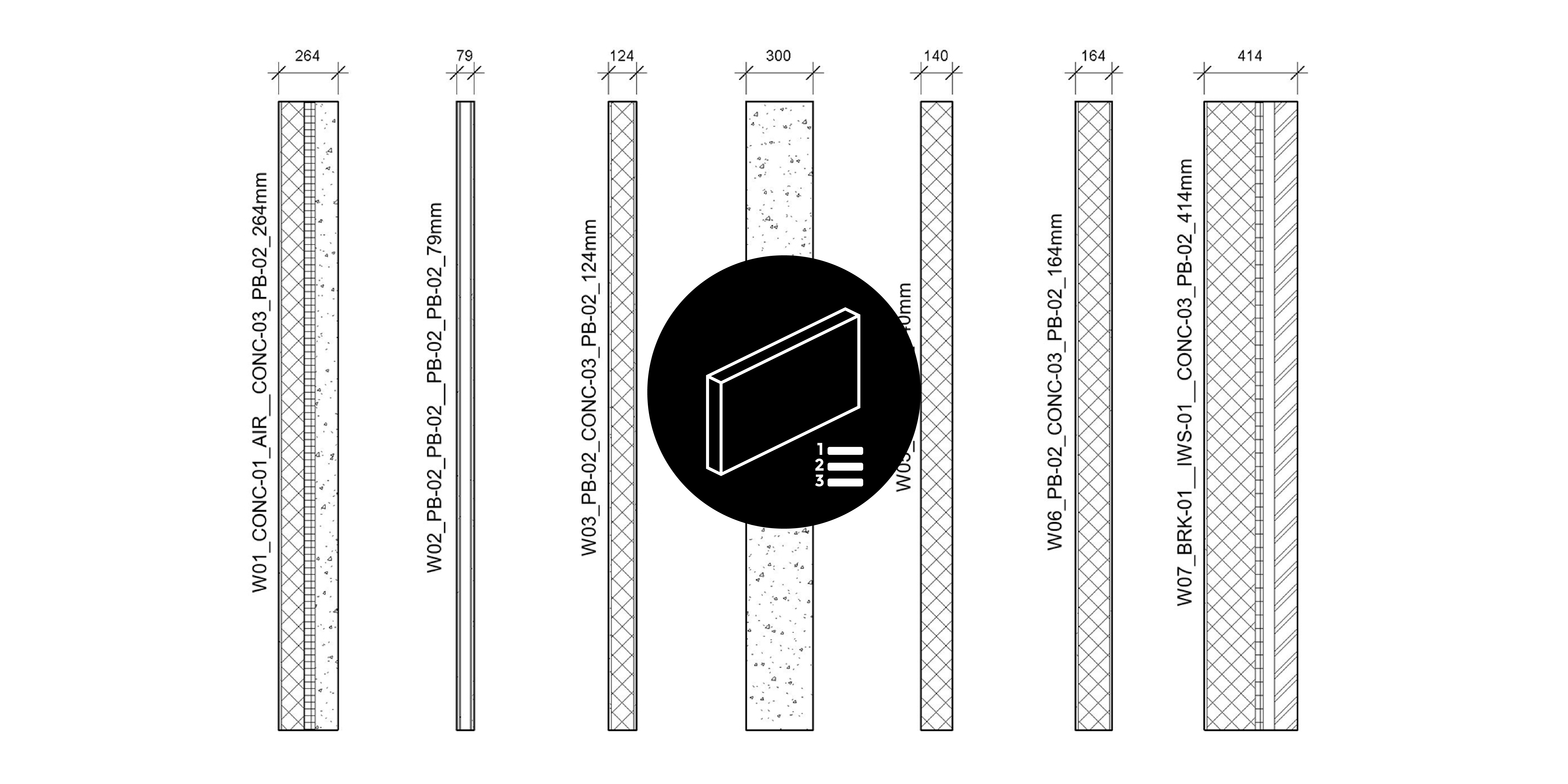
The graph collects all wall types in the project and filters them based on whether the wall type identifier value is present. That is, if the wall type doesn’t have a Type Mark or Keynote value, as identified in input #2, it is excluded. Next, each layer in the compound wall assembly is returned, and its associated material is calculated. Then, depending on input #3, the material’s Mark or Keynote value is returned. If no material is defined or the material is set to <By Category>, the graph will use the empty value replacement text (input #5). Next, the graph calculates the overall width and if there are wall layers outside of the ‘Core Boundary’ zone to determine its classification – raw, lining or finished. Finally, depending on the naming convention method (input #1), the values are concatenated together, and the wall type is renamed. For example, ‘W01_CONC-01_AIR_CONC-03_PB-02_264mm’.
Conclusion
When documenting, architects have historically used codes as a means to increase flexibility, efficiency and consistency. However, with the emergence of automated routines, such as those afforded by Dynamo, it is possible to improve legibility and reduce human error. To find out more about our Dynamo Package Development service, drop us a line and discover how we can automate your Revit workflows.


