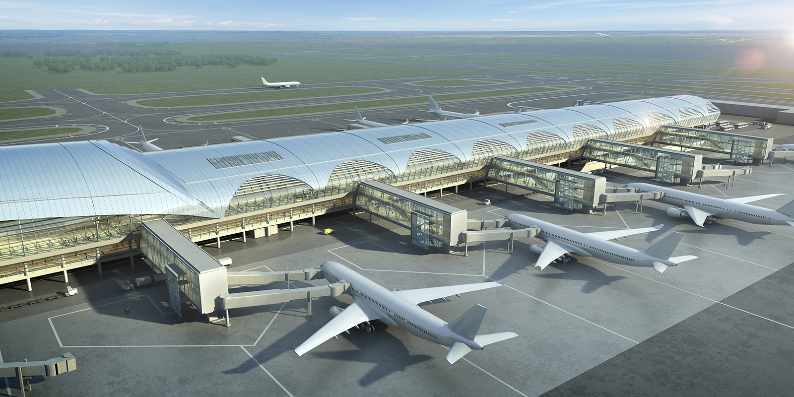

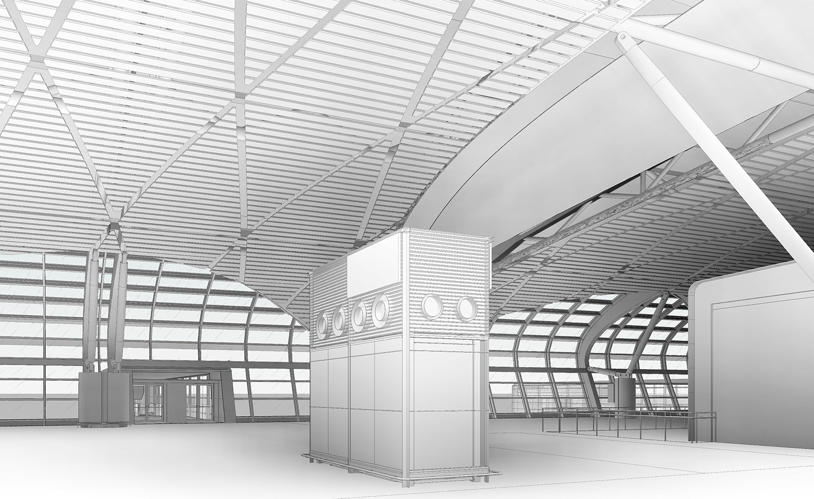
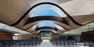
Airports of Thailand commissioned a consortium that included HOK as lead designer to design the new Suvarnabhumi International Airport Midfield Satellite Concourse in Bangkok. The 216,000m2, four-story concourse building will add 28 contact gates to Thailand’s main airport, which will serve more than 50 million passengers per year. The design references the existing architectural language of the main terminal. Using a similar barrel-vaulted section and alternating bands of glass and solid material, the interior of the midfield blends harmoniously with the spatial quality of the main terminal. The roof at the centre of the concourse is elevated and separated from the rest of the concourse; a reference to the stacked and layered roof forms of traditional Thai structures.
Computational process
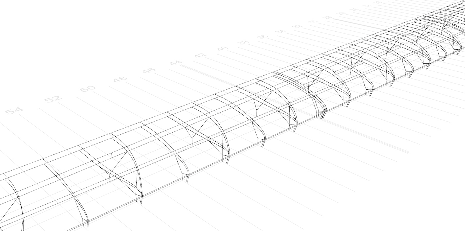
Initial conceptual design studies were first undertaken using McNeel’s Rhinoceros 5.0. These studies culminated in a wireframe model which defined the structural setting-out of the entire concourse. Due to a lack of computational skills within the project team, this was manually produced as opposed to using Grasshopper. Once the initial Rhino conceptual design studies were complete, the entire model was rebuilt from scratch using Autodesk Revit 2013. As it will be shown, this proved to be very tedious and ultimately unsuccessful, as Revit was unable to replicate the Rhino setting-out geometry, which was critical to the project.

Essentially, there were three main geometric components to the project:
- The structural trusses of which there were two types, a ‘bow truss; and a ‘flat truss’;
- The overall shell massing which would form the basis of the roof, glazing and skylights; and
- The ceiling battens.
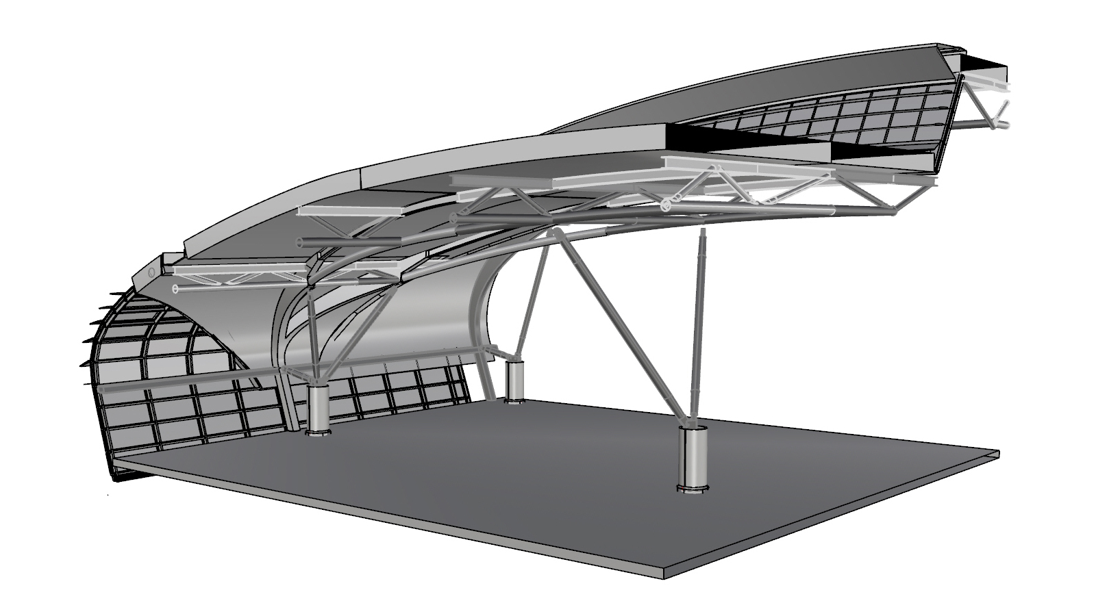
Structural trusses
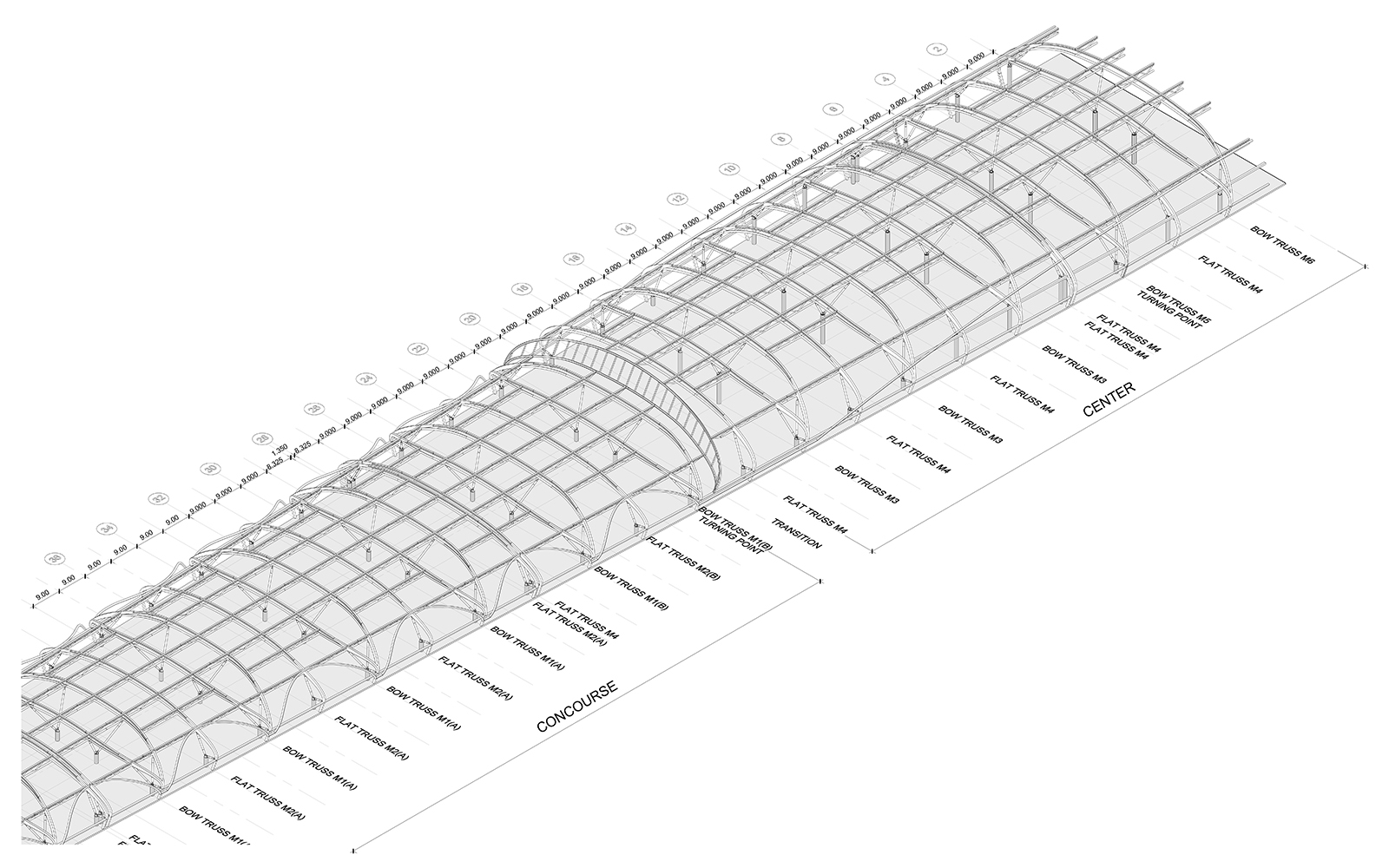
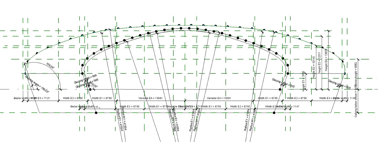
The structural trusses were generally pretty straightforward to model due to the geometric rationalisation that had already been undertaken in Rhino. The setting-out geometry was based on a series of tangential arcs in section which taper in plan. Key points were defined along these tangential arcs, which represented the ‘top of the top chord’ and the ‘bottom of the bottom chord’. This area was the structural zone with the roof build-up and ceiling situated above and below the region, respectively.
This process resulted in each bow truss and flat truss being standardised with only the middle truss varied to allow the building to taper in plan. Using a Revit generic model family, a series of type parameters were defined which allowed the truss to flex and the key setting-out points to be scheduled. Special attention was paid to the graphic representation of the complex geometry to aid legibility of the design intent.

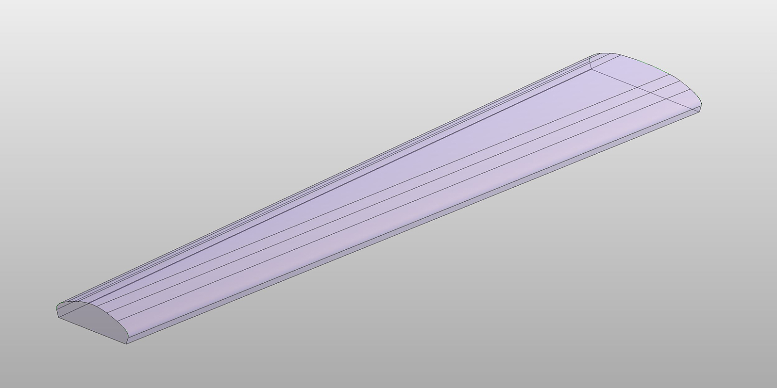
Overall shell massing
The concourse shell massing was initially rebuilt parametrically within a Revit conceptual mass family. Using the tangential arc profiles as defined above, these were lofted together to create various masses. There were several Revit conceptual mass families generated, including:
Bottom chord massing
Top chord massing
A series of void extrusions to subtract away various zones including window, gutters and transition zones.

Assembly massing
This was simply a compilation of all the masses into one file.
Revit’s tangential curve limitations
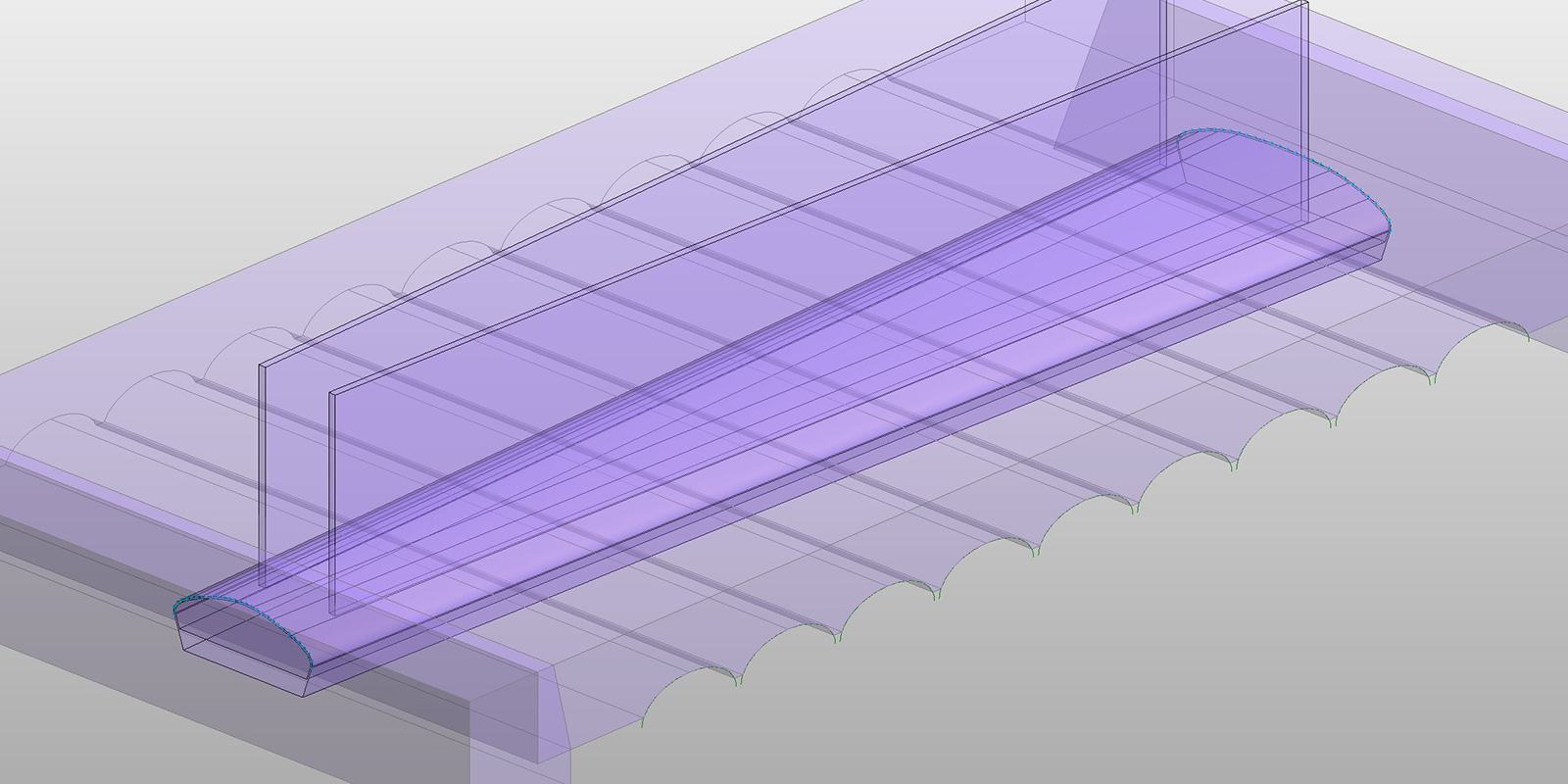
The assembly mass family was then loaded into the Revit project. Since the family defined the structural zone, a roof thickness needs to be applied above this zone. The ‘wall by face’ command was adopted, and initially, this proved to be successful in that Revit was able to read the segmented surfaces and produced individual walls. However, upon further investigation, it was discovered that all the surfaces needed to be tangential; otherwise, it resulted in inconsistent geometry, as shown below.

Due to an anomaly in our setting-out geometry, the two surfaces shown weren’t tangential. Without completely changing the master geometry, this proved to be a limitation of Revit that was unable to be overcome. Therefore, as an alternative to the ‘wall by face’ command, the project team explored building the entire roof massing as a single element within a conceptual mass family. All that was required was to use the top chord massing and offset the surface. Unfortunately, while this is a relatively straight forward procedure in Rhino, the Revit family editor wasn’t able to do this automatically. In what proved to be a painstakingly slow process, the project team offset all the reference lines and created new parameters before generating the new offset surface. However, this only fixed the first problem. The next challenge was that is was impossible to subtract the windows volumes accurately.
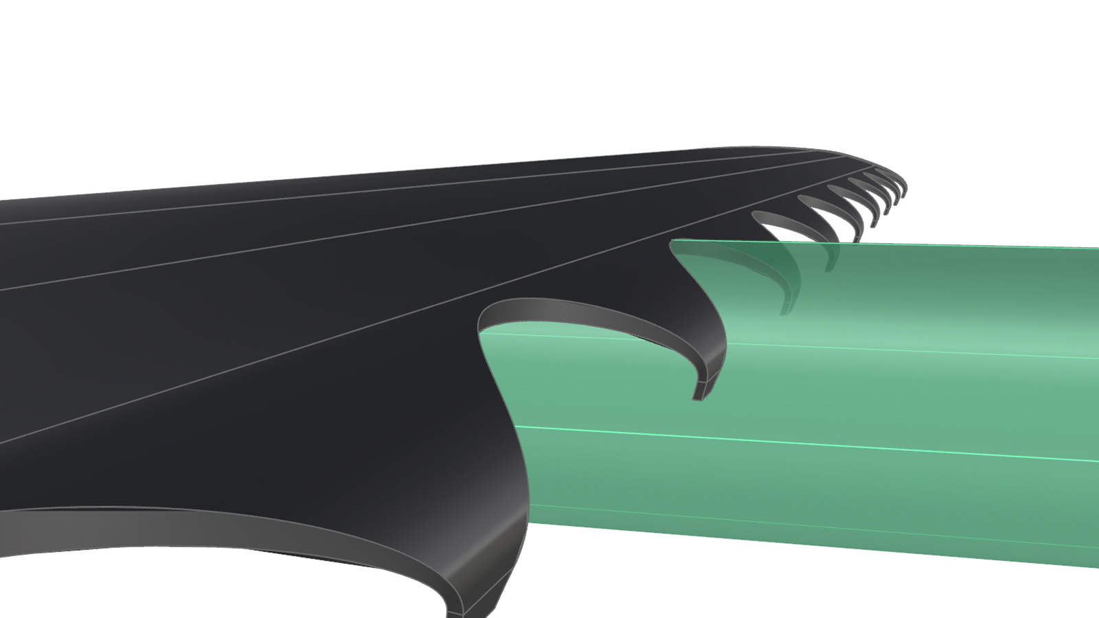
Boolean subtraction limitations
Using the Rhino’ offset surface’ command resulted in the edge of the window being perpendicular to the normal of the top chord surface, as shown below. However, using the void forms in Revit to perform a Boolean subtraction after the roof thickness had been generated would result in the edge of the window being parallel to the ground plane. This result was unacceptable, and consequently, this method was abandoned.
Rhino export
Eventually, after numerous unsuccessful tests in attempting to rebuild the Rhino shell geometry in Revit, it was decided to use the actual Rhino massing as the master geometry and import it directly into Revit using a *sat file via a conceptual mass family.

Of note is that when using Revit 2013, the *sat file was unable to be fully exploded, and if attempted, the imported geometry would disappear completely. However, when testing with Revit 2014, the geometry was able to be fully exploded. Since the project team was contractually tied to Revit 2013, the option of upgrading to Revit 2014 was unavailable. While exploding a *sat file within the conceptual mass family is not a pre-requisite for it to be functional, it does limit its adaptability if required.

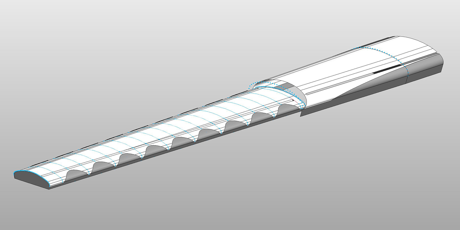
Ceiling battens
The other major computational issue the team faced was documenting the ceiling. Since in plan the building was tapering, the ceiling varied from structural bay to structural bay. A method needed to be developed to express and represent these variations. To achieve this, Chameleon and Grasshopper were adopted as there were no out-of-the-box Revit commands that would be able to replicate the design intent accurately.

The base surface was first created within Rhino. The surface was split at grid lines. This subdivision was done to compartmentalise troubleshooting as the script took approximately 10min to run per structural bay.

Grasshopper surface subdivision
Grasshopper was then used to divides the surface with UV divisions. Since the concourse tapered in plan, the divisions were calculated from the shortest length and based on critical dimension (batten width and min spacing, etc.). The centre lines were then offset to accommodate batten spacing.
A four-point surface was then created. However, these surfaces were not planar and needed to be rebuilt. The rebuilt surfaces were then extruded to give them a thickness and a Boolean operation used to cut out the arched window and skylight geometry.

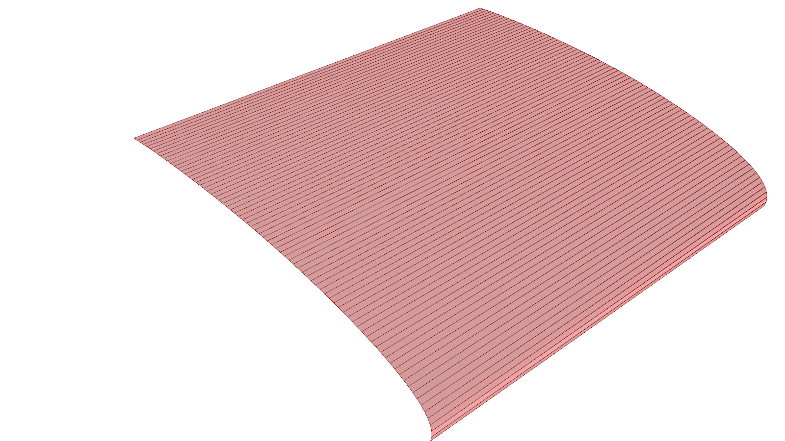
2D patterning
A 2D pattern was then created based on a sin curve and controlled through a grasshopper graph mapper component. This curve was then arrayed, offset, extruded and a Boolean operation performed on the battens.

Due to the Boolean operations described above, some of the resultant battens became quite small while others had more/fewer vertices. The Grasshopper script then culled the battens that were determined to be too small and filtered the reaming battens to be either 3-points, 4-points or 5- points battens (disregarding the batten thickness).
Adaptive components with Chameleon
Several adaptive components were then made within Revit to correspond with the number of vertices (3 points, 4 points, and 5 points) and loaded into the project. The thickness of the batten was controlled within the adaptive component as this reduced the number of placement points and hence made the script run faster.
The XYZ coordinates were then exported from Grasshopper via Chameleon. This export needed to be done in batches so that the appropriate adaptive component could be applied (3 points, 4 points, etc.) to the XYZ points being exported. It was discovered that the list of coordinates needed to be ‘cleaned’, as any empty lines would crash the export.

File management
The above method was very successful, albeit a little time-consuming. In all, there were approximately 13,000 individual battens for half the concourse. Rather than creating the entire ceiling, only half was created, and then when linked into the main model, it was copied and mirrored to minimise the computational load.
Conclusion
This case study highlighted Revit’s inability to deal with complex geometry. While it is always preferable to have entirely native Revit elements, this isn’t always possible as was shown here. Through the adoption of other software such as Rhino and Chameleon, it is possible to extend Revit’s capabilities and achieve the desired geometric outcome. With a clear workflow, geometric integrity and rigour can be maintained. Of course, for this to be successful, the project team needs to be sufficiently skilled in the proposed software, and if not, adequate training and support needs to be provided.


16 Comments
Santiago Rivera
Great Case Study!!!
Two years ago, working on a Frank’s Gerhy Abu Dahbi Guggenheim video for 4D construction planning, we agreed on Digital Project tender data received (Catia heritage) capabilities on working with complex surfaces, while maintaining BIM conceptual features. Really I think Revit stills has a lack on working with this kind of surfaces. While Rhino+Grasshopper and industrial design programs (Fusion 360, Onshape, Alias familiy, PTC, Inventor, Solidworks, etc) has all of this resolved due their geometry kernels, Architectural programs haven’t resolved this on a fluent and straight forward way.
paulwintour
Hi Santiago. Yes I completely agree. Some people get super excited at Revit’s possibilities but actually if you look at other programs, like Rhino, there is still much Revit can’t do.
Claudio Vittori Antisari
Hi Paul,
i don’t want to sand presumptuous stating that to me that workflow can deliver in Revit using Dynamo, but i cannot keep that for me. All the geometrical issues that you are point out were really real in 2013, with Revit 2013 and no Dynamo. But nowadays there is Dynamo and is a game changer for handling complex geometries in Revit. Do you think that now is be possible to manage this kind of geometry in Revit and Dynamo, or you still need Rhino?
paulwintour
Hi Claudio
This case study was documented in 2014 but I recently presented it at RTC Australia to supplement my presentation on interoperability (which I’ll post shortly). I don’t think it is obsolete. Yes, quite a few of the issues we faced back in 2013/2014 could be resolved with Dynamo today. Revit 2017 now has tangency locks which would have made generating the base massing much easier. The ceiling and adaptive components could definetely have been replaced with Dynamo.
But my rational for including it in my RTC presentation was to promote the idea of interoperability. Somethings are just easier and faster to do in another software, such as Grasshopper. So what’s the point fighting it, trying to do everything natively in Revit? Ultimately they all come in as the same objects (adaptive components, import instances/ direct shapes, etc).
There are still many bugs and limitations with Dynamo. Simple things like offsetting polycurves and intersecting calculations. (https://github.com/DynamoDS/Dynamo/issues/6156#issuecomment-216727248 & https://github.com/DynamoDS/Dynamo/issues/5681#issuecomment-184470675). So while in theory we could replicate everything with Dynamo, it’s likely we would discover new issues/bugs which would complicate the workflow. It’s hard to know unless I actually repeat the process in Dynamo, which I have no intention to do so. Maybe check out my upcoming post on interoperability and then decide if you agree.
claudiovittoriantisari
Hi Paul,
Thank for answering me, i agree 100% with the interoperability concept. The difficult thing is to find a simple workflow most of the time. Still when it comes to the Rhino-Revit debate, i’m a little skeptical. Rhino is a superior modelling tool but some times i see people giving up with data and buildability in order to achieve a complex shape. There are cool workflow that allow you the simplify the process without loosing valuable data and some other that are just “cutting the angles” to get to that shape. After seeing your next post on interoperability i’m sure you belong to the first group. Thank for you clarification again.
Davide Madeddu
Great work Paul! We worked with Chamaleon with lot of headaches..but finally it works ad you shown. Now we are trying Rhynamo and finally Flux and the last seem a very good platform to exchange data via Rhino/Revit. Are there some people in BVN working with it?
paulwintour
Hi Davide. Chameleon is dead. I found it fantastic because it worked so well and was much faster than the other plug-ins like Hummingbird. I use Rhynamo all the time now and have just started getting into Flux. There are already some tutorials on Rhynamo on my site and I’ll be posted some on Flux soon. I have an interoperability post that I’ll publish shortly. It documents the history of these plug-ins and it’s interest to see patterns in their developments.
paulwintour
In case you guys are interested here is a link to my post about interoperability: https://parametricmonkey.com/2016/06/20/bim-ecosystem/
yhshui@gmail.com
This is a very nice Case Study to showcase the digital design process. I am an Architect living in Bangkok and I couldn’t help but notice (during my rent trips to the BKK airport), that the metal roof, the curved profile (where kalzip metal roof meets glazed facade) is cut by hand, strip by strip to form the curvature, perhaps the construction is yet to be completed. From the case study, the design shows a panalized roof surface, should the roof system(s) be pre-fabricated (similar to the Sage Music Centre, UK, by Fosters) roof panels that consist of exact curvatures repeated, rather than kalzip strips? There seems to be dislocation between the design and the actual construction. I am eager to see the final result.
paulwintour
Hi. Thanks for the feedback. I was only involved in the Design Development phase. Not sure how it has been fabricated/constructed. Since it was D+C, I’m sure there has been some modifications but I can’t say what or why. Here are some recent site photos though: https://www.facebook.com/Thailand.Infra/posts/747927845645697
Yann Hui
Thanks for that, really helpful to understand the design further.
Yann Hui
The design is also similar to the Mid-field Concourse at Hong Kong International Airport, design by Aedas.
paulwintour
In what way?
Yann Hui
Overall form, spatial planning and function, slight difference for the roof detailing.
krist
Hi Paul,
Kinda late to the party, but here is my account from the fabrication side:
https://www.linkedin.com/posts/krist-mututanont-920b6b2a6_activity-7286012268021006336-ZXUo?utm_source=social_share_send&utm_medium=member_desktop_web
It’s pretty ironic that much of my work on the project boiled down to working to de-Revit the project files. How I wished I’ve found this website earlier so we could’ve just both skip Revit altogether!
Paul Wintour
Wow, thanks for sharing Krist. Always good to see how projects end up. The design was done back in 2013 and not completed until late 2023. Lots has changed over the past decade. But yes, certainly, it would have been far easier to go directly from the Grasshopper concept script to the Grasshopper fabrication script and avoid Revit altogether. This is how most of the projects I’m working on now work, and it is far, far better.