
The ultimate guide to digital fabrication models
A best practice guide with key concepts and tips for creating digital fabrication models using Grasshopper and Rhino.


Creates worksets based on your naming convention. If required, the default worksets can also be renamed. Note that before you can run the script, you’ll need to enable worksharing manually.

Automates the creation of unplaced rooms en mass based on an Excel spreadsheet. The Excel file should contain the Room Name values. Additional instance parameters, such as Department or Occupant, can also be customised.

Creates 3D views to visually verify that elements are on the correct workset by isolating the workset in visibility graphics. If additional worksets are added after the views were created, re-run to update the workset visibility in all views.

Creates sheet sets based on selected views in the Project Browser. For example, it will take the General Arrangement (GA) floor plans, duplicate the views, rename the views and assign the correct view template to create Reflected Ceiling Plans (RCP), Concrete Profile Setout Plans, etc.

Generates blank sheets from an Excel file. The Excel file should contain the Sheet Name and Sheet Number values. The user will be able to decide which title block is to be applied. If additional instance parameters are to be populated, such as Drawn By or North Point visibility, then this can be customised.

Takes the selected views in the Project Browser, groups them based on a naming convention, and places them onto new sheets. Note that for views to be grouped, the views must have a consistent view naming convention. Placement of views is based on a basic grid setout. For accurate viewport alignment (once placed), use the align viewports tool.
Create internal elevations per room for orthogonal walls. If the room contains non-orthogonal walls, a separate elevation marker is placed per wall and automatically rotated so that it is perpendicular to the wall.

Creates marketing floor plans for each apartment. The views are cropped to the bounding box of the apartment, inclusive of any external balconies or terraces.

Takes the marketing plans and places them onto unique sheets. The title block parameters, including key plan visibility and north point rotation, are also updated.

Sets the properties of title block family instances.

Substitutes the title blocks family located on selected sheets. This is useful when switching sheet sizes, say from A3 to A1.
Renumbers rooms sequentially based on a (model) spline. Only rooms that intersect the curve will be processed. This allows for batch processing which is often desirable. The number padding can then be set. For example, no padding will result in 0, 1, 2 etc., whereas a 2-digit padding will result in 00, 01, 02, etc. An optional prefix, such as the level number, can also be set.
Due to SEPP65 requirements, it is often necessary to know which balcony is associated with which apartment. This graph will rename balcony rooms with a suffix based on the apartment room number. This allows for easier scheduling and compliance testing.

Renames rooms based on the model group that is located within. This is useful as often apartment model groups are decoupled from the party walls and façades. This graph thus allows for the room and the model group to be in sync.
Moves selected rooms to the room's centroid location. If the room is odd-shaped and the centroid falls outside the room boundary, the original room location is retained.
Takes selected rooms and modifies their properties so that the upper limit is based on the level above rather than an unbounded height.
Renumbers doors based on the room in which it is located. For example, Element prefix - Room number - Sequence number (D-101-01).

Renumbers windows based on the room in which it is located. For example, Element prefix - Room number - Sequence number (W-101-01).

Rename wall types based on the wall build-up. The graph calculates each wall layer’s thickness and its material code and then renames the wall type based on this sequence.

Sequentially renames orthogonal grids numerically or alphanumerically, preventing the error: “The name entered is already in use. Enter a unique name.”

Moves door tags from their default location, which corresponds to the door’s insertion position, to within the swing of the door for clearer, graphic representation.

Generates annotations for stairs, both in plan and section, by creating dimensions, number systems, spot elevations, stair run tags and minimum clearance zones. The graph works best on standard stairs or typical stairs, which are grouped and copied up.

Synchronises room parameters nested within a model group. Parameter must be instance based and set to ‘values can vary by group instance’.

Automates the naming of rooms based on area thresholds. For example, name all rooms '1 BED' if its area is between 50 - 69m2.
Creates a callout based on the room's outline or an axis-aligned (orthogonal) bounding box.

Generates an axonometric view with a section box based on a room's bounding box. Views can be orientated NE, SE, SW or NW.

Applies graphic overrides to obscuring walls and dependent doors and window families in selected axonometric views. Useful for stylising room data sheet views.
Extract the perimeter of a filled region with the ability to calculate only certain line styles within the boundary.
Calculates the width and length of a golden mean rectangle given an area. Includes the ability to create certain elements, such as Filled Regions with those proportions.

Adjusts the crop region of selected axonometric (orthographic) views so that the extents match the elements visible in the view, including any buffer offset specified.

Generates a multi-category schedule with a filter, returning all elements in the room. Useful for Room Data Sheets.

Moves room tag to the room location point. Use in combination with Centre Room Location.

Renumbers viewports by grouping them into rows or columns, before sorting them. Renumber process prevents the error: “The name entered is already in use. Enter a unique name.” The Detail Number parameter can be renumbered numerically or alphanumerically, with optional digit padding, e.g. 01.

Assigns elements to a workset based on its category and/or properties, for example, exterior or interior walls. The graph can be re-run multiple times to ensure every element is on the correct workset and that views display as intended.

Renames selected views, schedules and sheets from the Project Browser to be uppercase.

Duplicates selected views in the Project Browser and renames them with a prefix or suffix. This workflow is useful for batch-creating working views that are properly organised and separated from production views.

Aligns viewports on sheets based on a template sheet to ensure that all sheets have a consistent graphic layout to them. Excludes legend and schedule alignment.

Batch add revisions to selected sheets, saving precious time when issuing drawing.

Deletes all direct shapes in the project. This is necessary when updating direct shapes, as any direct shape with an identical name in the project will cause the file to crash.

Checks for problems with rooms, such as self-intersecting boundaries, and should be run prior to any other room-based graphs.

Substitutes an element's line style for another, before deleting the old line style from the model.

Sets multiple view’s underlay parameter to none so that when printing, the view will display as required.

Collects all unused view filters in the model with the option of deleting them.

For SEPP65 compliance it is important to know the dimensions of balconies and if they satisfy the minimum dimension as defined in the Apartment Design Guide. This graph checks compliance and assigns a yes/no value to the room’s shared parameter.

Generates a series of 3D views based on a time period, for example 9am - 3pm on 21 June. This is useful for visual verification for SEPP65 solar access requirements.
Checks all stairs in the model and tests for maximum riser height, minimum going length, maximum number of risers, and minimum clearance width.

Generates a 2D isovist in the form of a filled region to analyse the fitness of a view from a specific vantage point.
A best practice guide with key concepts and tips for creating digital fabrication models using Grasshopper and Rhino.
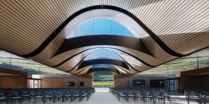
The Macarthur Memorial Park is an exemplar of digital fabrication, with each building’s self-similar soffit parametrically derived.

Six technological forces – Becoming, cognifying, flowing, screening, accessing and remixing – are challenging many long-held assumptions.

If you can’t measure it, you can’t manage it. But how should AEC organisations identify what matters and then measure it?
