The ultimate guide to digital fabrication models
A best practice guide with key concepts and tips for creating digital fabrication models using Grasshopper and Rhino.
A best practice guide with key concepts and tips for creating digital fabrication models using Grasshopper and Rhino.
Use Dynamo to automatically renumber the detail number parameter of viewports placed on sheets, streamlining documentation.
Learn how to use Dynamo to batch update the crop region of axonometric views with a consistent buffer offset.

Learn how to use Dynamo to automate the batch creation of multi-category schedules for use in a room data sheet.

Use Dynamo to automatically place a single or multiple views onto a new sheet, such as for room data sheets.

Use Dynamo to automatically apply graphic overrides to obscuring walls in an axonometric view for use in a room data sheet.

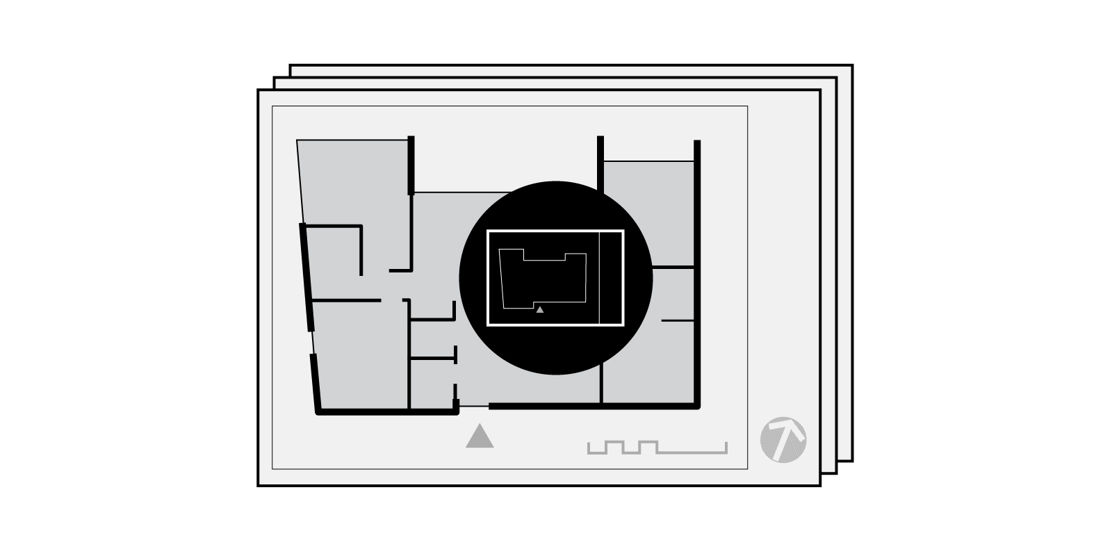
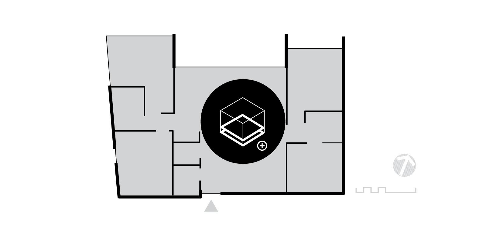
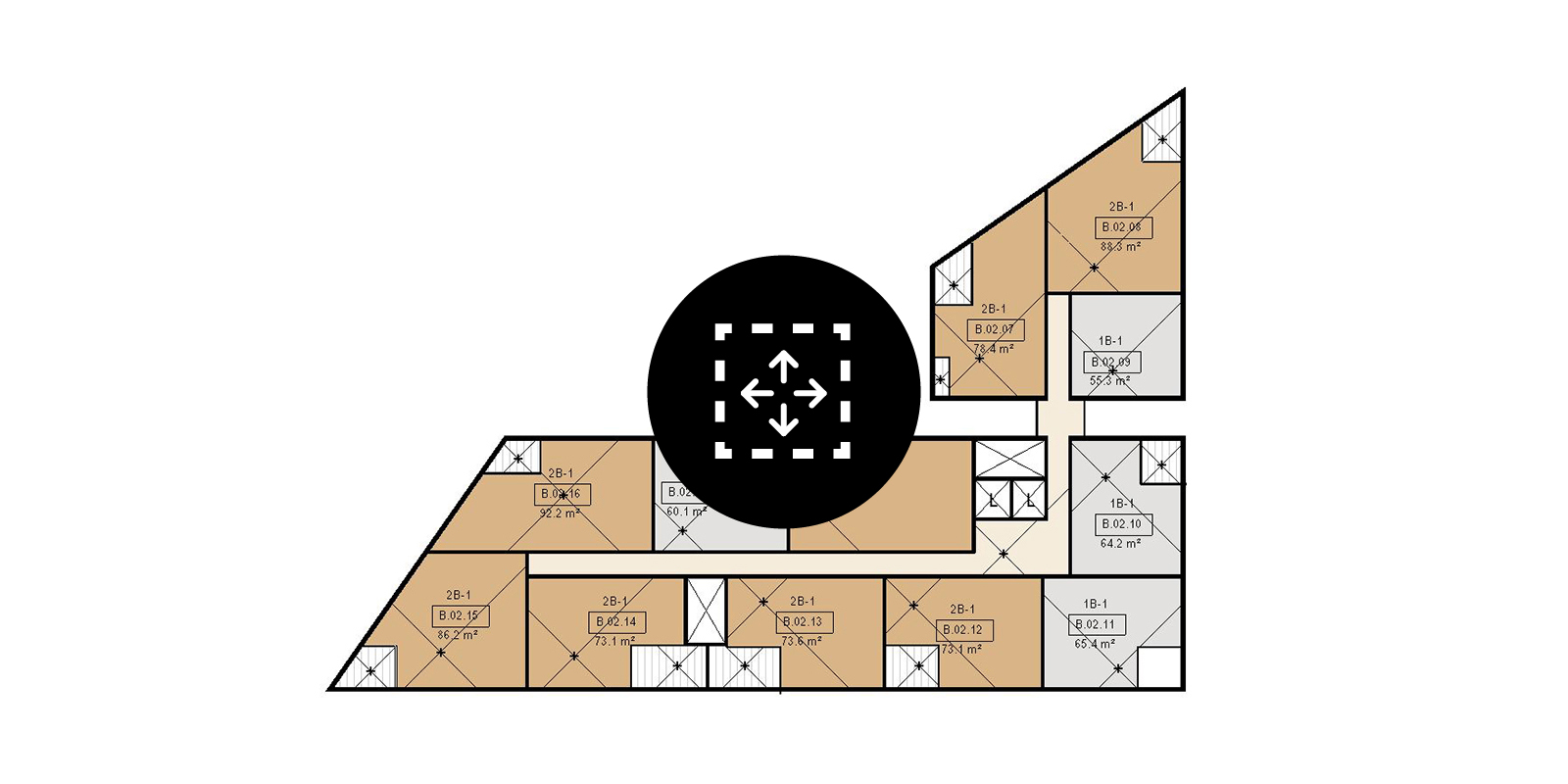
Automate the batch creation of axonometric views based on the room’s bounding box for use in a room data sheet.

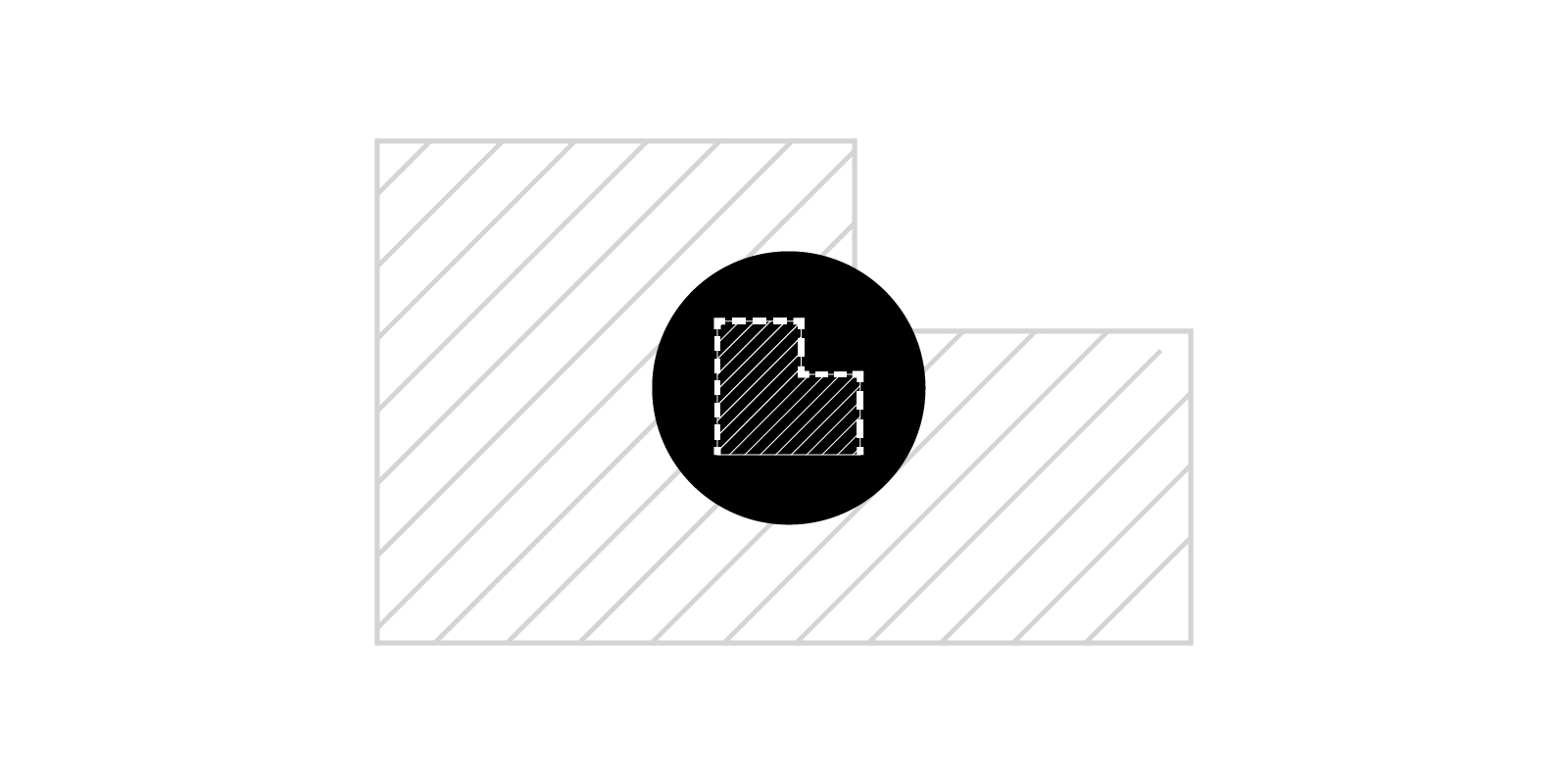
Learn how to use Dynamo to automate the batch creation of axis-aligned callouts based on the room’s bounding box.

Learn how to automate the renumbering of Revit windows based on the room in which it is located using Dynamo.

Use Dynamo to create isolated workset views to verify that Revit elements are on their correct workset.

A simple Dynamo workflow for adding or removing a revision to multiple sheets simultaneously in Revit 2022 or lower.

Generate elevation markers and corresponding internal elevation views using Dynamo based on rooms and their bounding wall’s orientation.

A Dynamo workflow to synchronise instance-based room parameters, such as apartment number, nested within a Revit model group.

Learn some of the key differences between Dynamo and Rhino.Inside Revit and discover the benefits of migrating certain Dynamo workflows to Rhino.Inside Revit.

Learn how to run a detailed solar access analysis in Revit with Rhino.Inside Revit and Ladybug Tools for SEPP65 compliance.
Learn how to generate views from the sun using Rhino.Inside Revit to visually verify the results of a Ladybug solar access heatmap.

Verify a balcony’s minimum area and depth with Dynamo for compliance with the NSW Apartment Design Guide and SEPP65 requirements.

A Dynamo workflow to renumber balconies based on their associated apartment room to assist in documentation and compliance checking.
Automatically place marketing plans onto individual sheets and set the various title block properties with Dynamo.
A workflow to automatically create marketing plans with Dynamo, including cropping and rotating the views.

A Dynamo workflow to automatically create Revit sheet sets/ drawing series, based on a pre-created set.
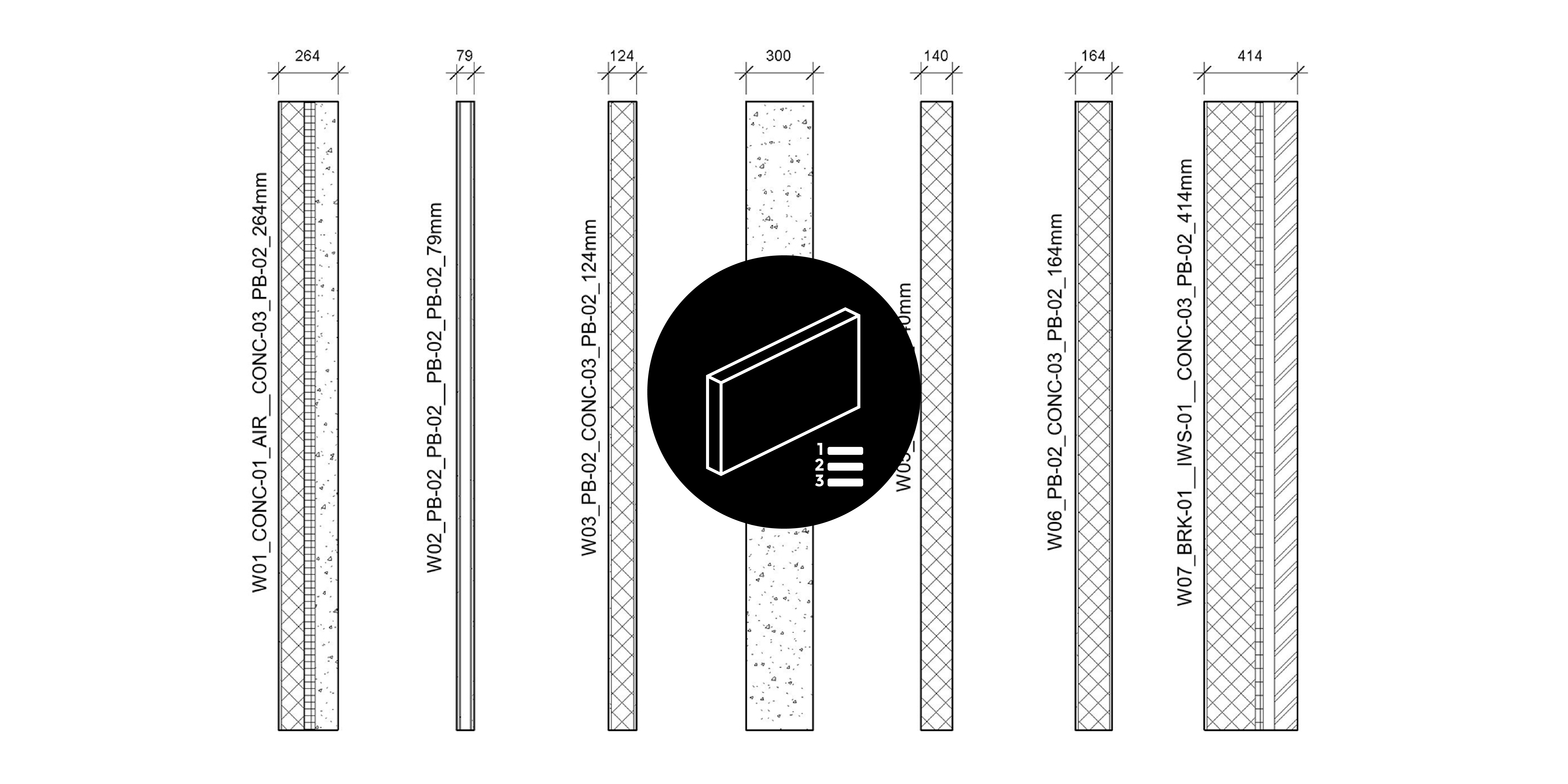
A Dynamo workflow to automatically rename Revit wall types based on their layer build-up and function.
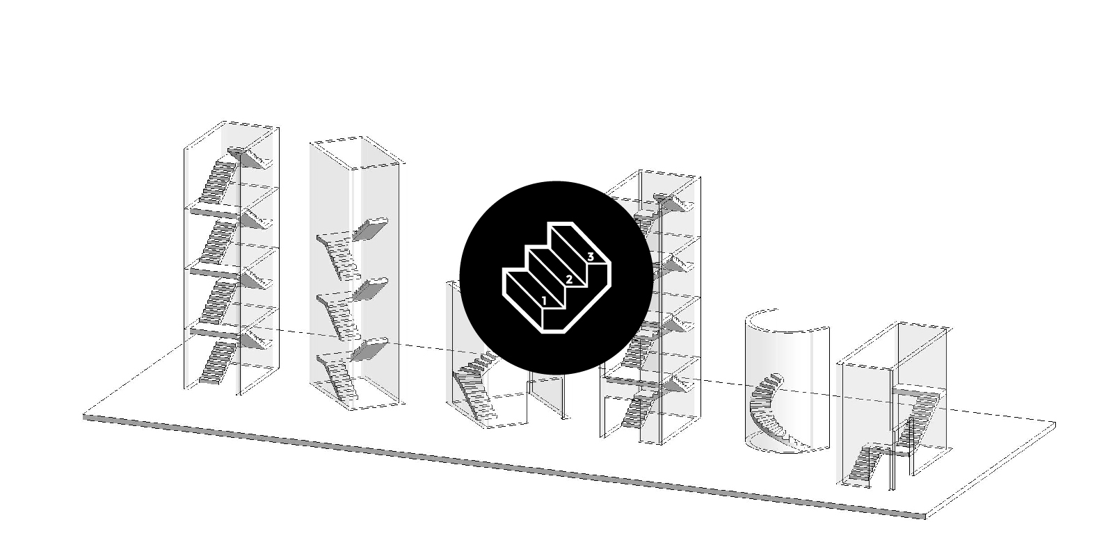
A Dynamo workflow to document stairs by creating dimensions, number systems, spot elevations, stair run tags & min clearances.
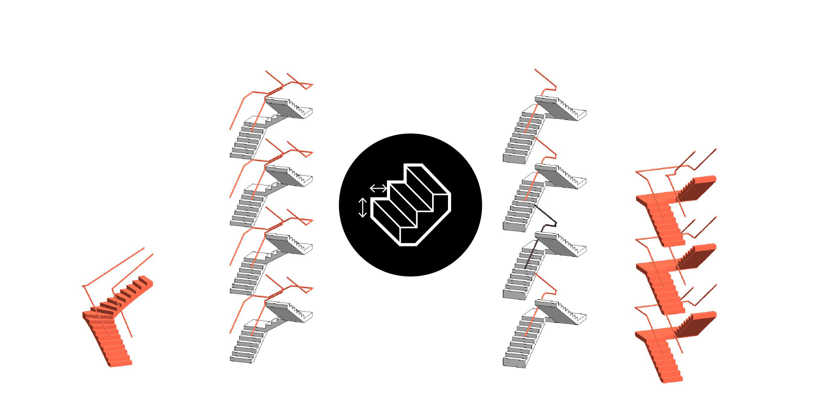
Verify stairs compliance including riser height, going length, risers per stair run & clearance between top rails.

Automatically align viewports across multiple sheets using Dynamo for a consistent graphic layout.

Identify rooms in Revit which are unplaced or have self-intersecting or multiple boundaries.

Substitute an element’s line style for another, before deleting the old line style from the model.

Modify door tags so that they are located within the swing of the door, for clearer graphic representation.

Explore Autodesk Insight and run various illuminance-based lighting analyses including solar access.
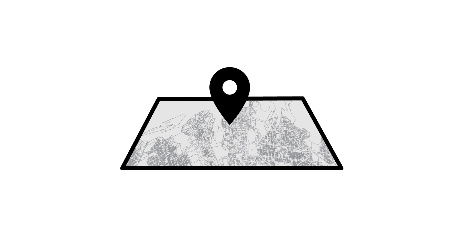
Learn how to geo-reference your Revit model based on survey or Geographical Information System (GIS) data sets.

Learn about the various geographic and projection coordinate systems used within Australia including GDA2020.

Learn how to install Rhino.Inside and reference Revit geometry so that you can run Grasshopper scripts within Revit.

Automate a stadium seating bowl using Dynamo and understand the key requirements in the Green Guide including sightlines and c-values.

Learn how to rename views, sheets & schedules with Dynamo, to ensure they are all uppercase.
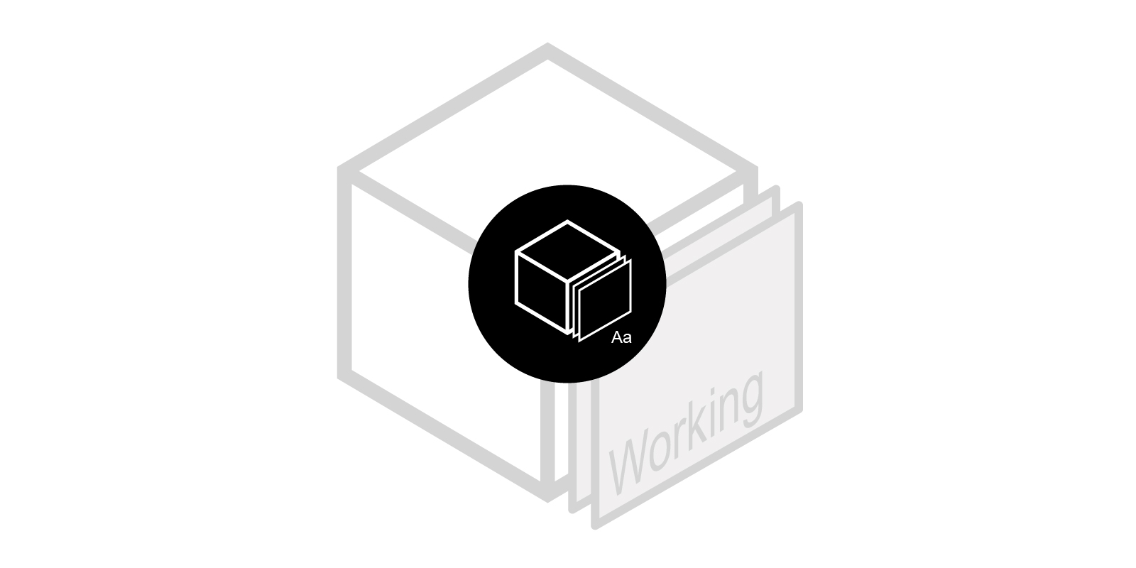
Use Dynamo to duplicate views and rename them as working views for better Project Browser organisation.

Learn how to automatically renaming grids using Dynamo and avoid “The name entered is already in use” error.
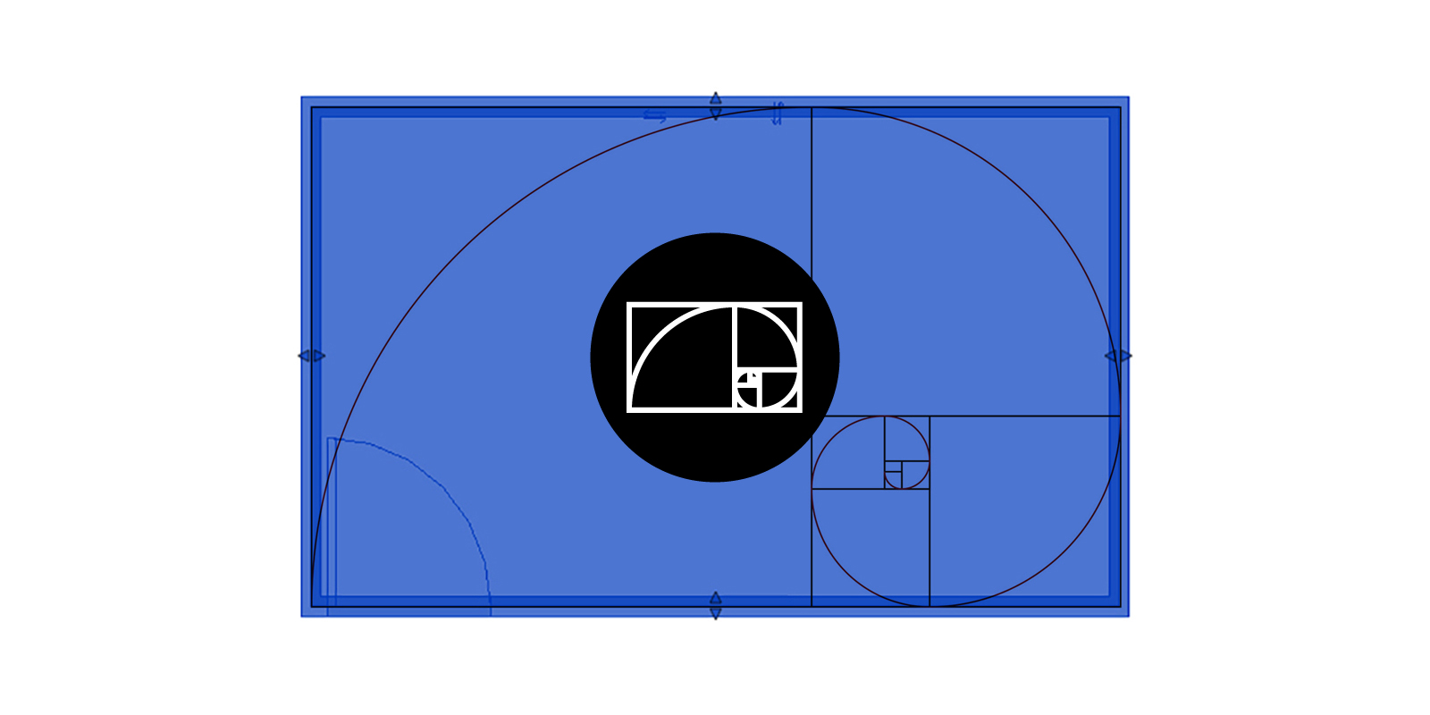
Calculate the width and length of a golden mean rectangle in Dynamo, given the area as an input.

Automatically create empty sheets from Excel using Dynamo and the out-of-the-box ‘Sheet.ByNameNumberTitleBlock’ node.

Learn how to assign Revit model elements to their correct workset using an Excel spreadsheet and Dynamo.

Learn how to create worksets and rename the default worksets using Dynamo to automate the central model setup process.
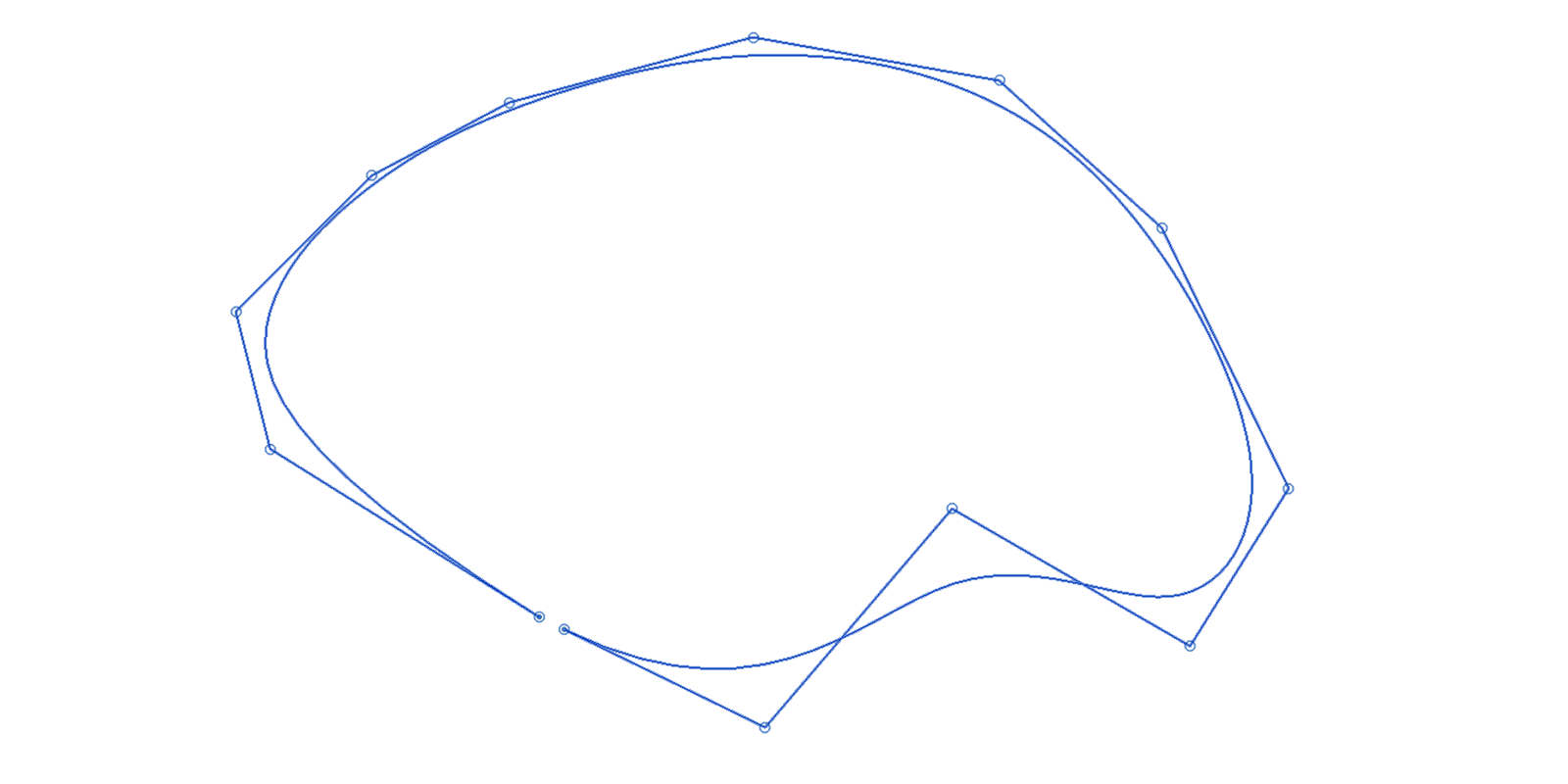
Discover the limitations of working with splines in Revit and how to overcome them with these workarounds.

A brief introduction into some of the 2D detailing tools at your disposal to embellish your 3D Revit model.

This tutorial demonstrates how to enable worksharing in a Revit model for team collaboration and file size management.
Learn how to create a 2D isovist view analysis in Dynamo and embed the results into Revit using filled regions and project parameters.

Learn about the various types of annotations within Revit including tags, dimensions, keynotes and schedules.

A beginners introduction in how to get started with Revit including CAD underlays, setting up grids & levels, & conceptual modelling.

Discover Revit’s startup location and its importance in establishing a shared coordinate system when working with interoperability plug-ins.
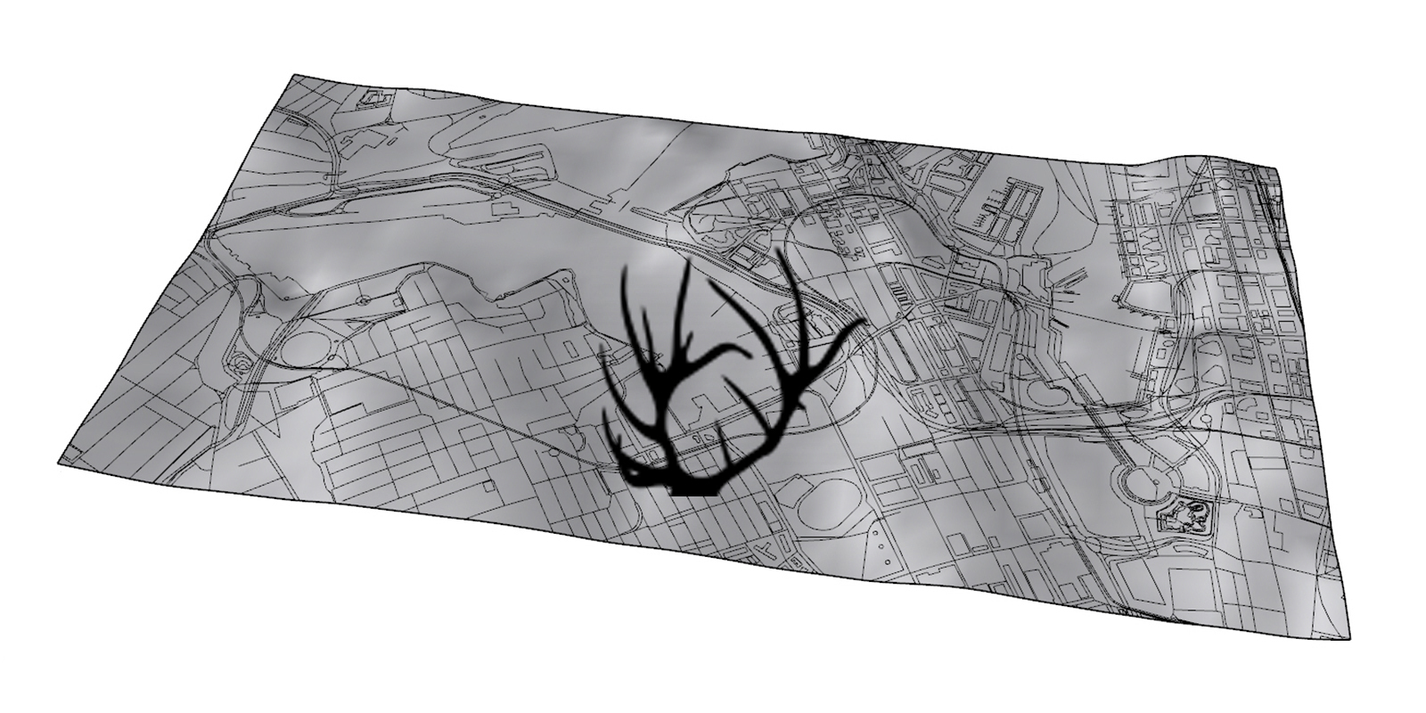
Discover Elk and how to generate 3d map info in grasshopper from Open Street Map (OSM) and Shuttle Radar Topography Mission (SRTM) data.
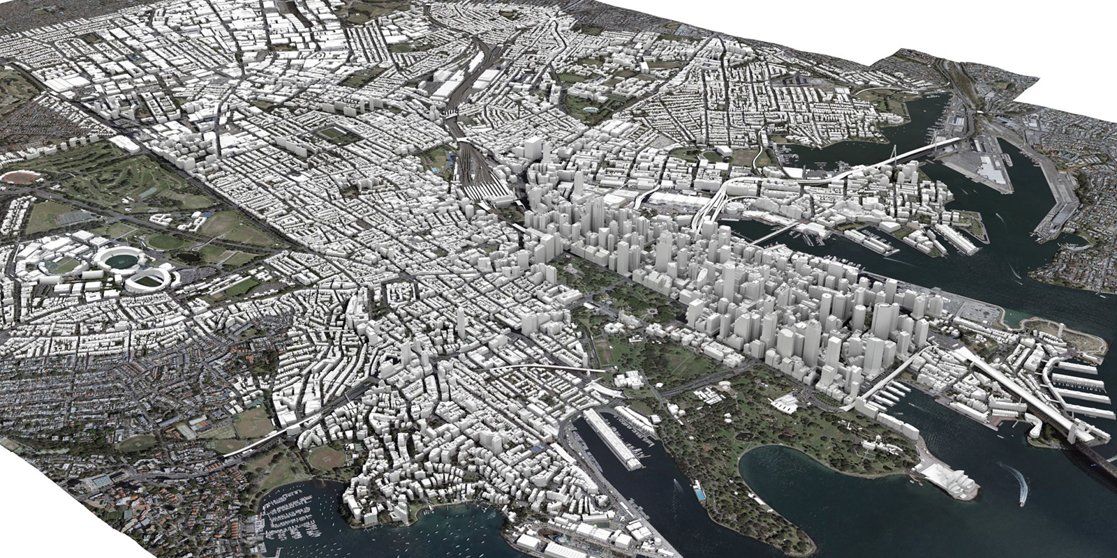
Learn about geographic and projected coordinate systems and how to setup up a City of Sydney digital model from AAM.
Discover how to extract the perimeter of a filled region in Revit using Dynamo and filtered line styles.

Learn how to generate views from the sun with Dynamo to visually verify the results of a Ladybug solar access heatmap.
Learn about Elefront, the Grasshopper plug-in focused on managing model data in Rhino to create a ‘Soft BIM’ model.
Discover Ladybug & Honeybee, the plug-ins for Grasshopper to help create environmentally-conscious designs.

Discover about fractals and L-Systems and how to generate these in Grasshopper using HoopSnake and Rabbit.

Learn how to generate a 2D and 3D electromagnetic field in grasshopper using the flowL plug-in.

Use Dynamo to extract all the unused filters in your Revit project so that they can be purged for file maintenance.
Discover eTransmit, the best method for purging and cleaning up a central Revit model so that it can be easily shared.

Discover how to use Dynamo to batch automate the substitution of title blocks family types located on Revit sheets.
Master how to move Revit rooms and room tags to the centroid of the room using Dynamo.

Compare the options available in Grasshopper to undertake a view analysis, including using 2D isovists, 3D isovists and a Ladybug heat map.

Understand the importance of sharing your screen and discover Grasshopper’s shortcuts and hotkeys.

Download this pdf primer which contains tips and translations to help migrate your Grasshopper skills to Dynamo.

Extract Revit rooms for a detailed SEPP65 solar access compliance analysis in Ladybug and push results back into Revit.

Learn to create and animate a catenary curve/membrane using Grasshopper and Kangaroo’s live physics engine.

This tutorial explores how you can translate levels from Rhino to Revit using Excel and Dynamo.

Learn how to use Dynamo to automate the creation of unplaced rooms in Revit from an Excel spreadsheet.

Learn how to undertake a SEPP65 solar access compliance analysis for residential projects using Grasshopper and Ladybug.

Discover Karamba, the structural analysis plug-in for Grasshopper and how to calculate lateral displacement.
Discover how to update the instance parameters of a Revit titleblock families using Dynamo.

Learn how to globally control a Revit view’s underlay parameter so that when printing, the view will display as required.

Learn the limitations of creating an elliptical stair in Revit and how to overcome them using Grasshopper.
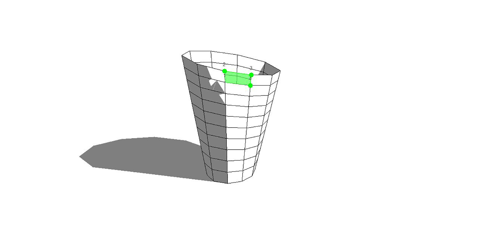
Understand the limitations of using Revit’s divided surface command on planar trapezoidal surfaces.

Forget the hype, learn the fundamentals – 16 tips for best practice modelling in Autodesk Revit.
This tutorial explores how you can translate geometry from Rhino to Revit via Excel using an adaptive component family.

Export grids from Grasshopper to Excel and generate native Revit grids using Dynamo.

Learn how to convert Revit areas (GBA, GFA, etc) into import instances using the ‘Area.ImportInstance’ node in Dynamo.

Batch automate the adjustment of a room’s upper limit in Revit by using Dynamo.

Discover how to automate the naming of Revit rooms based on area thresholds using Dynamo.

Learn how to synchronise Revit model groups and rooms with Dynamo to ensure efficient multi-residential documentation.

Learn how to automate the renumbering of Revit doors based on the room in which it is located using Dynamo.

Use the ‘Room.ImportInstance’ node within Dynamo to convert Revit rooms into 3D objects.

Learn how to batch renumber Revit rooms sequentially based on a guiding model line using Dynamo.

This is a list of best practice workflows to follow when generating Rhino massing for import into Revit.
